DS75LV Ver la hoja de datos (PDF) - Maxim Integrated
Número de pieza
componentes Descripción
Fabricante
DS75LV Datasheet PDF : 14 Pages
| |||
DS75LV
Digital Thermometer and Thermostat
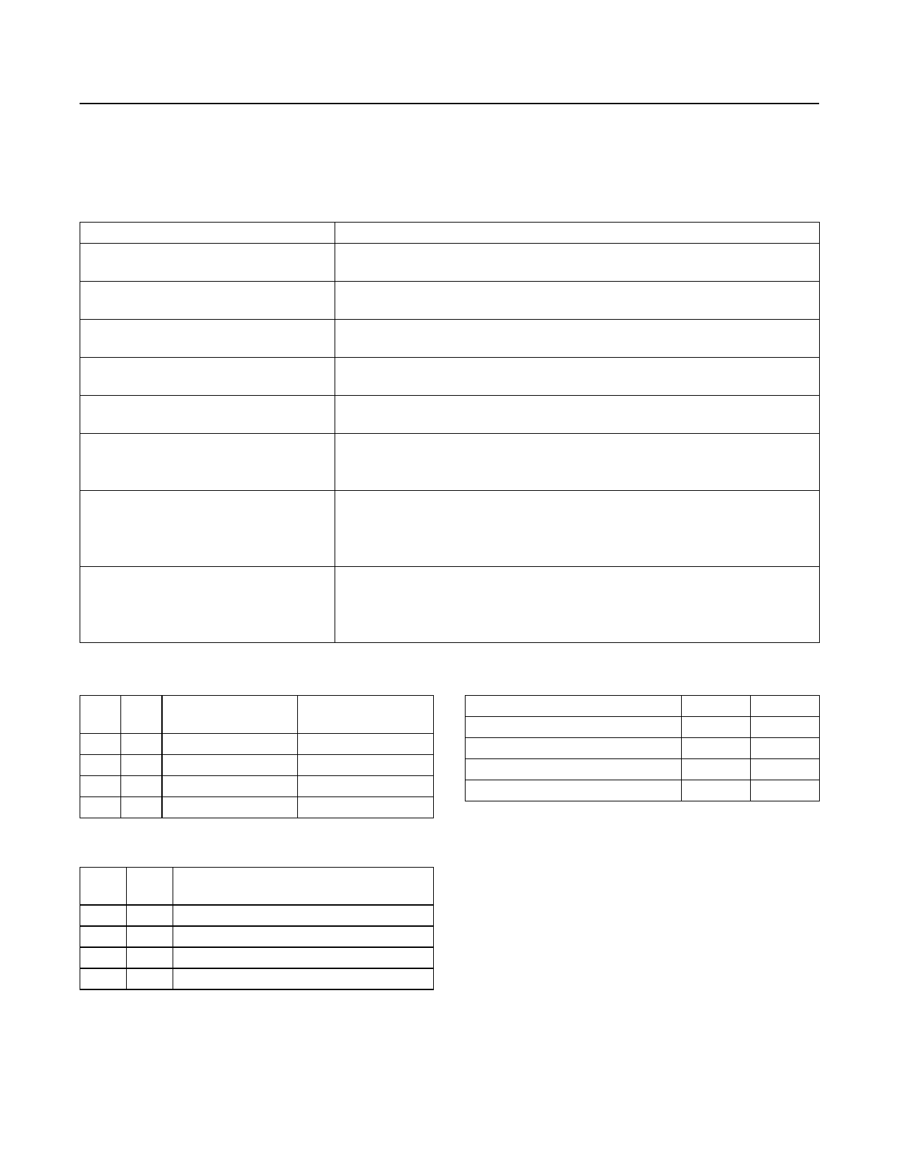
Table 2. Configuration Register Bit Descriptions
BIT NAME
0
Reserved
R1
Conversion Resolution Bit 1
R0
Conversion Resolution Bit 0
F1
Thermostat Fault Tolerance Bit 1
F0
Thermostat Fault Tolerance Bit 0
POL
Thermostat Output (OS) Polarity
FUNCTION
Power-up state = 0
The master can write to this bit, but it will always read out as a 0.
Power-up state = 0
Sets conversion resolution (see Table 3)
Power-up state = 0
Sets conversion resolution (see Table 3)
Power-up state = 0
Sets the thermostat fault tolerance (see Table 4).
Power-up state = 0
Sets the thermostat fault tolerance (see Table 4).
Power-up state = 0
POL = 0 — OS is active low.
POL = 1 — OS is active high.
TM
Thermostat Operating Mode
Power-up state = 0
TM = 0 — Comparator mode
TM = 1 — Interrupt mode
See the Thermostat section for a detailed description of these modes.
SD
Shutdown
Power-up state = 0
SD = 0 — Active conversion and thermostat operation.
SD = 1 — Shutdown mode.
See the Shutdown Mode section for a detailed description of this mode.
Table 3. Resolution Configuration
R1 R0
0
0
0
1
1
0
1
1
THERMOMETER
RESOLUTION
9-bit
10-bit
11-bit
12-bit
MAX CONVERSION
TIME (ms)
25
50
100
200
Table 4. Fault Tolerance Configuration
F1
F0
0
0
0
1
1
0
1
1
CONSECUTIVE OUT-OF-LIMITS
CONVERSIONS TO TRIGGER OS
1
2
4
6
Table 5. Register Pointer Definition
REGISTER
Temperature
Configuration
THYST
TOS
P1
P0
0
0
0
1
1
0
1
1
www.maximintegrated.com
Maxim Integrated │ 8
Share Link: 