DS2409 Ver la hoja de datos (PDF) - Dallas Semiconductor -> Maxim Integrated
Número de pieza
componentes Descripción
Fabricante
DS2409 Datasheet PDF : 18 Pages
| |||
DS2409
remaining deselected. This significantly speeds up the analysis of topology and population in a
continuously changing network. The coupler also supports the bus master in detecting arrivals on the
inactive segments of the network by responding to the conditional search command. The control output
can be used to optically signal the on/off state of a branch or, together with the auxiliary output, for
handshaking in dual-master applications. The network size can be maximized by using a DS2480 line
driver at the bus master’s serial interface. The DS2480 compensates for the rising ground level caused by
the non-zero on-resistance of couplers in multi-level networks.
OVERVIEW
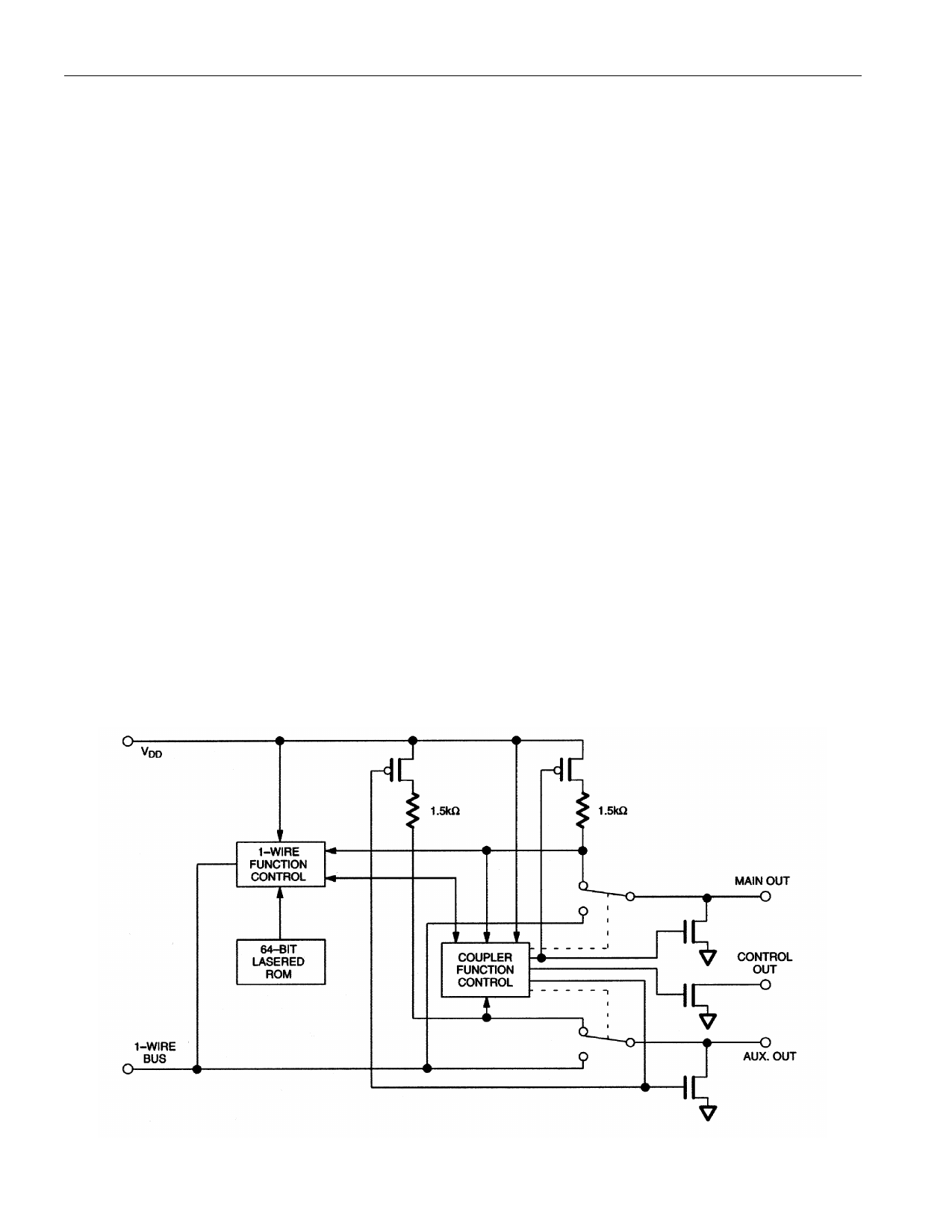
The DS2409 Coupler provides a means to create large MicroLAN networks with additional control
capability provided by an open-drain N-channel MOSFET that can be remotely switched via
communication over the 1-Wire bus (Figure 1). An auxiliary output can be used to label the branch by
connecting a programmed 1-Wire memory chip or as digital input. The DS2409 contains a factory-lasered
registration number that includes a unique 48-bit serial number, an 8-bit CRC, and an 8-bit family code
(1FH). The 64-bit ROM portion of the DS2409 not only creates an absolutely unique electronic
identification for the device itself but also is a means to locate and address the device in order to exercise
its control functions.
The DS2409 uses the standard Dallas Semiconductor 1-Wire protocol for data transfers (Figure 2), with
all data being read and written least significant bit first. Communication to and from the DS2409 requires
a single bi-directional line that is typically a port pin of a microcontroller. The 1-Wire bus master
(microcontroller) must first issue one of five ROM function commands: 1) Read ROM, 2) Match ROM,
3) Search ROM, 4) Skip ROM, or 5) Conditional Search ROM. These commands operate on the 64-bit
lasered ROM portion of each device and can singulate a specific device if many are present on the 1-Wire
line as well as indicate to the bus how many and what type of each device is present. After a ROM
function command is successfully executed, the control functions of the device can be exercised via the 1-
Wire bus.
BLOCK DIAGRAM Figure 1
2 of 18
102199
Share Link: 