DS2108 Ver la hoja de datos (PDF) - Dallas Semiconductor -> Maxim Integrated
Número de pieza
componentes Descripción
Fabricante
DS2108 Datasheet PDF : 5 Pages
| |||
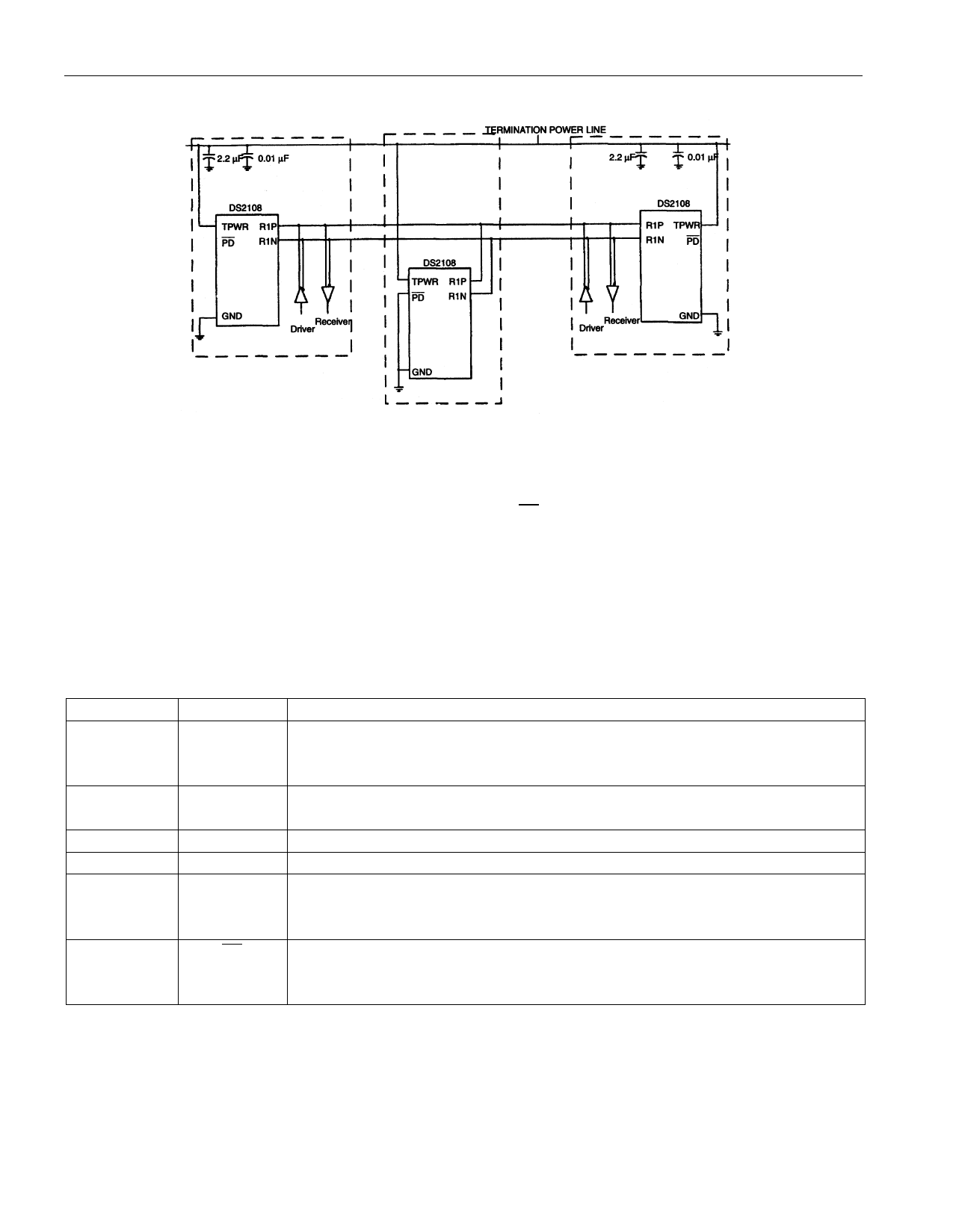
TYPICAL DIFFERENTIAL SCSI BUS CONFIGURATION Figure 2
DS2108
NOTES:
1. Two DS2108s required per 8–bit SCSI device and three DS2108s per 16–bit SCSI device.
2. Mid–bus termination effectively removed by grounding PD pin.
3. Termination power to be provided as specified in SCSI–3 Parallel Interface (SPI) document.
4. Local TERMPWR bypassing is recommended by the SPI document with values shown. The bypass
capacitors should be located as close as possible to the DS2108s. Only one pair of capacitors is
required per SCSI device (may be shared between DS2108s on same device).
PIN DESCRIPTION Table 1
PIN
SYMBOL DESCRIPTION
1, 11
TPWR Termination Power. Should be connected to the SCSI TERMPWR line.
Bypass with a 2.2 µF cap in parallel with a 0.1 µF cap as shown in Figure
2.
2, 3, 4, 5, 6, R1N…R9N Signal Termination Negative. Connect to –SIGNAL of SCSI bus.
7, 8, 9, 10
12
NC
No Connect. Do not connect any signal to this pin.
13, 23
GND Ground. Signal ground; 0.0V.
14, 15, 16, R1P…R9P Signal Termination Positive. Connect to +SIGNAL of SCSI bus.
17, 18, 19,
20, 21, 22
24
PD
Power Down. When tied low, the DS2108 enters a power-down mode.
Contains an internal 50K pull-up. Strap low to deactivate the DS2108,
leave open circuited to activate the DS2108.
3 of 5
Share Link: 