DS1996 Ver la hoja de datos (PDF) - Dallas Semiconductor -> Maxim Integrated
Número de pieza
componentes Descripción
Fabricante
DS1996 Datasheet PDF : 18 Pages
| |||
DS1996
for more than 16 µs (Overdrive Speed) or more than 120 µs (regular speed), one or more of the devices
on the bus may be reset.
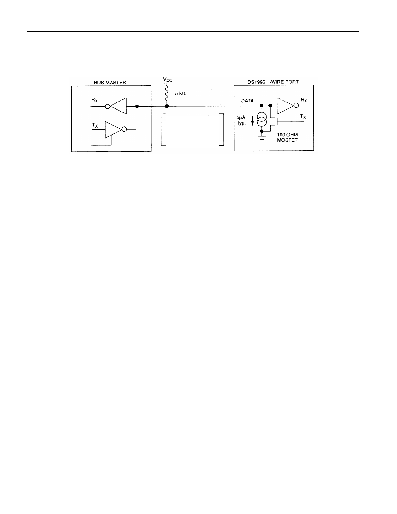
HARDWARE CONFIGURATION Figure 8
Rx= RECEIVE
Tx = TRANSMIT
TRANSACTION SEQUENCE
The protocol for accessing the DS1996 via the 1-Wire port is as follows:
§ Initialization
§ ROM Function Command
§ Memory Function Command
§ Transaction/Data
INITIALIZATION
All transactions on the 1-Wire bus begin with an initialization sequence. The initialization sequence
consists of a reset pulse transmitted by the bus master followed by presence pulse(s) transmitted by the
slave(s).
The presence pulse lets the bus master know that the DS1996 is on the bus and is ready to operate. For
more details, see the ”1-Wire Signaling” section.
ROM FUNCTION COMMANDS
Once the bus master has detected a presence, it can issue one of the six ROM function commands. All
ROM function commands are eight bits long. A list of these commands follows (refer to flowchart in
Figure 9).
Read ROM [33H]
This command allows the bus master to read the DS1996’s 8-bit family code, unique 48-bit serial
number, and 8-bit CRC. This command can only be used if there is a single DS1996 on the bus. If more
than one slave is present on the bus, a data collision will occur when all slaves try to transmit at the same
time (open drain will produce a wired-AND result). The resultant family code and 48-bit serial number
will usually result in a mismatch of the CRC.
10 of 18
Share Link: 