DM9368 Ver la hoja de datos (PDF) - Fairchild Semiconductor
Número de pieza
componentes Descripción
Fabricante
DM9368 Datasheet PDF : 6 Pages
| |||
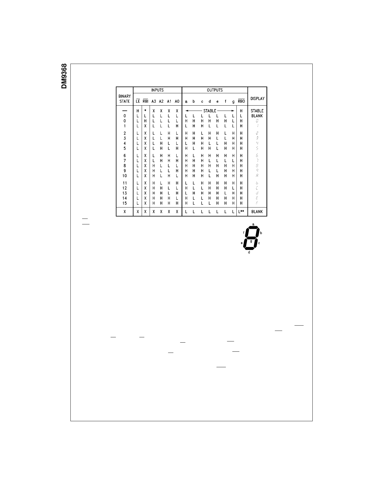
Truth Table
*The RBI will blank the display only if a binary zero is stored in the latches.
*The RBO used as an input overrides all other input conditions.
H = HIGH Voltage Level
L = LOW Voltage Level
X = Immaterial
Functional Description
The DM9368 is a 7-segment decoder driver designed to
drive 7-segment common cathode LED displays. The
DM9368 drives any common cathode LED display rated at
a nominal 20 mA at 1.7V per segment without need for cur-
rent limiting resistors.
This device accepts a 4-bit binary code and produces out-
put drive to the appropriate segments of the 7-segment dis-
play. It has a hexadecimal decode format which produces
numeric codes “0” thru “9” and alpha codes “A” through “F”
using upper and lower case fonts.
Latches on the four data inputs are controlled by an active
LOW latch enable LE. When the LE is LOW, the state of
the outputs is determined by the input data. When the LE
goes HIGH, the last data present at the inputs is stored in
the latches and the outputs remain stable. The LE pulse
width necessary to accept and store data is typically 30 ns
which allows data to be strobed into the DM9368 at normal
TTL speeds. This feature means that data can be routed
directly from high speed counters and frequency dividers
into the display without slowing down the system clock or
providing intermediate data storage.
Another feature of the DM9368 is that the unit loading on
the data inputs is very low (−100 µA Max) when the latch
enable is HIGH. This allows DM9368s to be driven from an
MOS device in multiplex mode without the need for drivers
on the data lines.
The DM9368 also has provision for automatic blanking of
the leading and/or trailing edge zeros in a multidigit decimal
number, resulting in an easily readable decimal display
conforming to normal writing practice. In an eight digit
mixed integer fraction decimal representation, using the
automatic blanking capability, 0060.0300 would be dis-
played as 60.03. Leading edge zero suppression is
obtained by connecting the Ripple Blanking Output (RBO)
of a decoder to the Ripple Blanking Input (RBI) of the next
lower stage device. The most significant decoder stage
should have the RBI input grounded; and since suppres-
sion of the least significant integer zero in a number is not
usually desired, the RBI input of this decoder stage should
be left open. A similar procedure for the fractional part of a
display will provide automatic suppression of trailing edge
zeros. The RBO terminal of the decoder can be OR-tied
with a modulating signal via an isolating buffer to achieve
pulse duration intensity modulation. A suitable signal can
be generated for this purpose by forming a variable fre-
quency multivibrator with a cross coupled pair of TTL or
DTL gates.
www.fairchildsemi.com
2
Share Link: 