DG447 Ver la hoja de datos (PDF) - Vishay Semiconductors
Número de pieza
componentes Descripción
Fabricante
DG447 Datasheet PDF : 13 Pages
| |||
DG447, DG448
Vishay Siliconix
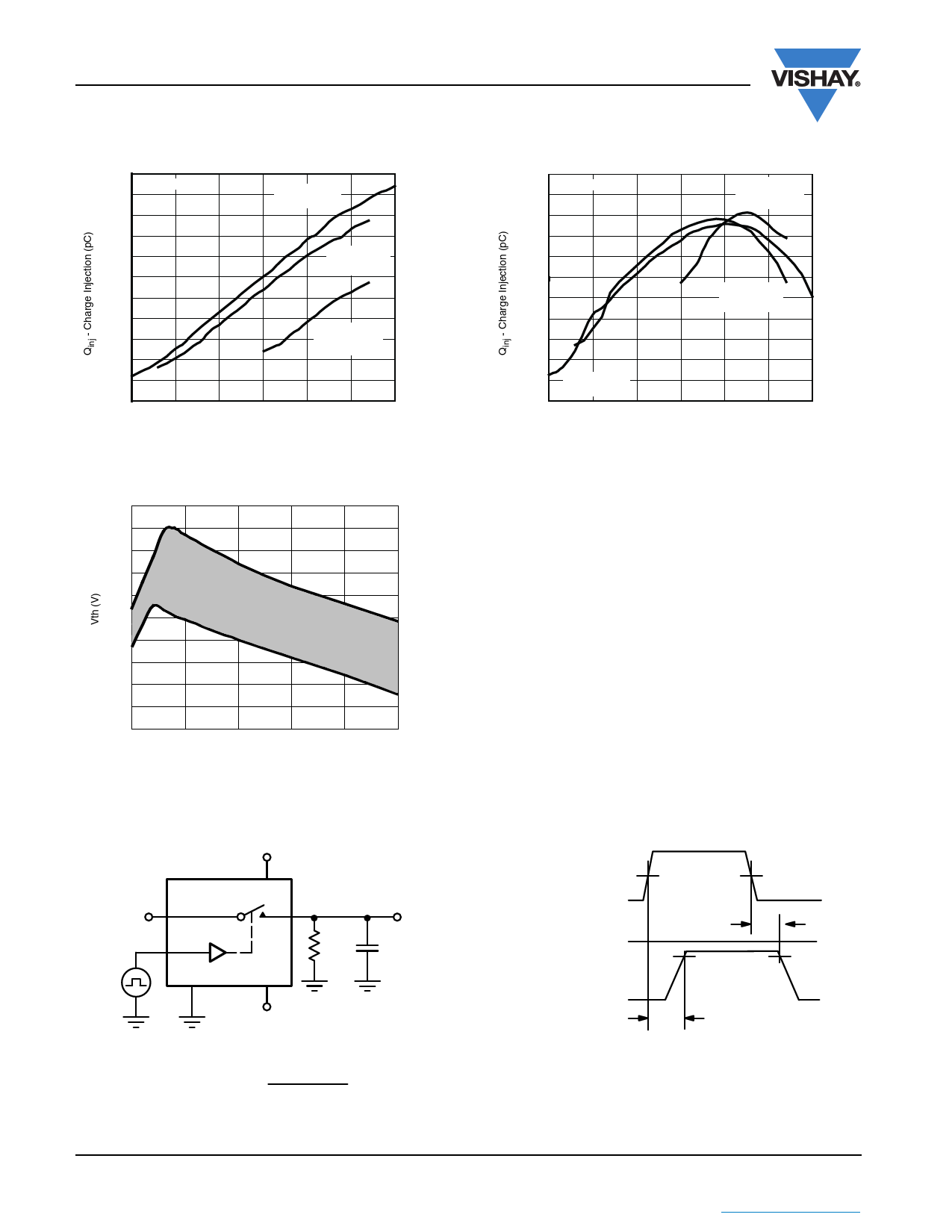
TYPICAL CHARACTERISTICS (TA = 25 °C, unless otherwise noted)
160
CL = 10 nF
140
120
V+ = + 15 V
V- = - 15 V
100
80
V+ = + 12 V
V- = - 12 V
60
40
20
0
V+ = + 12 V
V- = 0 V
- 20
- 40
- 60
- 15 - 10
-5
0
5
10
15
Analog Voltage (V)
Charge Injection vs. Analog Voltage
(Measured at COM pin)
150
CL = 10 nF
100
50
V+ = + 12 V
V- = 0 V
0
- 50
- 100
- 150
- 200
V+ = + 12 V
V- = - 12 V
- 250
- 300
- 350
- 400
- 15
V+ = + 15 V
V- = - 15 V
- 10
-5
0
5
Analog Voltage (V)
10
15
Charge Injection vs. Analog Voltage
(Measured at NC or NO pin)
2.5
2.3
2.1
1.9
1.7
1.5
1.3
1.1
0.9
0.7
0.5
5
10
15
20
25
30
V+ (V)
Input Switching Threshold vs. Supply Voltage
TEST CIRCUITS
VO is the steady state output with the switch on.
+ 15 V
10 V
NO/NC
IN
GND
V+
COM
V-
RL
300 Ω
VO
CL
35 pF
Logic
3V
Input
0V
50 %
Switch
VS
Input
VO
90 %
tr < 20 ns
tf < 20 ns
tOFF
- 15 V
Switch
0V
Output
tON
CL (includes fixture and stray capacitance)
VO = VS
RL
RL + rON
Note: Logic input waveform is inverted for switches that have the
opposite logic sense.
Figure 1. Switching Time
www.vishay.com
Document Number: 73854
6
S11-1336-Rev. D, 04-Jul-11
This document is subject to change without notice.
THE PRODUCTS DESCRIBED HEREIN AND THIS DOCUMENT ARE SUBJECT TO SPECIFIC DISCLAIMERS, SET FORTH AT www.vishay.com/doc?91000
Share Link: 