HV301LG Ver la hoja de datos (PDF) - Supertex Inc
Número de pieza
componentes Descripción
Fabricante
HV301LG Datasheet PDF : 21 Pages
| |||
HV301/HV311
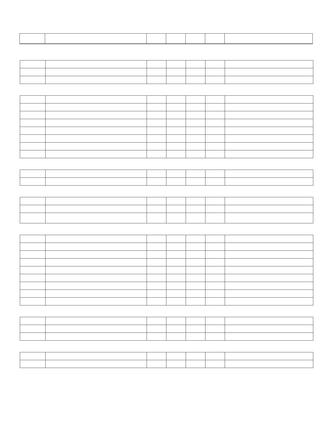
Electrical Characteristics (-10V ≤ VEE ≤ -90V, -40°C ≤ +85°C unless otherwise noted)
Symbol
Parameter
Min Typ Max Units
Conditions
Supply (Referenced to VDD pin)
VEE
Supply Voltage
IEE
Supply Current
IEE
Sleep Mode Suppy Current
OV and UV Control (Referenced to VEE pin)
-90
-10
V
600
700
µA VEE = -48V, Mode = Limiting
400
450
µA VEE = -48V, Mode = Sleep
VUVH
VUVL
VUVHY
IUV
VOVH
VOVL
VOVHY
IOV
UV High Threshold
UV Low Threshold
UV Hysteresis
UV Input Current
OV High Threshold
OV Low Threshold
OV Hysteresis
OV Input Current
Current Limit (Referenced to VEE pin)
VSENSE-CL Current Limit Threshold Voltage
VSENSE-CB Circuit Breaker Threshold Voltage
Gate Drive Output (Referenced to VEE pin)
VGATE
IGATEUP
Maximum Gate Drive Voltage
Gate Drive Pull-Up Current
IGATEDOWN Gate Drive Pull-Down Current
1.26
V Low to High Transition
1.16
V High to Low Transition
100
mV
1.0
1.26
nA VUV = VEE +1.9V
V Low to High Transition
1.16
V High to Low Transition
100
mV
1.0
nA VOV = VEE + 0.5V
40
50
60
mV VUV = VEE + 1.9V, VOV = VEE + 0.5V
80
100
120
mV VUV = VEE + 1.9V, VOV = VEE + 0.5V
8.5
10
500
40
12
V VUV = VEE + 1.9V, VOV = VEE + 0.5V
µA VUV = VEE + 1.9V, VOV = VEE + 0.5V
mA VUV = VEE, VOV = VEE + 0.5V
Ramp Timing Control (Test Conditions: CLOAD=100µF, CRAMP=10nF, VUV=VEE+1.9V, VOV=VEE+0.5V, External MOSFET is IRF530*)
IRAMP
Ramp Pin Output Current
10
tPOR
Time from UV to Gate Turn On
2.0
tRISE
Time from Gate Turn On to VSENSE Limit
400
tLIMIT
Duration of Current Limit Mode
5.0
tPWRGD Time from Current Limit to PWRGD
5.0
VRAMP
Voltage on Ramp Pin in Current Limit Mode
3.6
tSTARTLIMIT Start Up Time Limit
80
100 120
tCBTRIP Circuit Breaker Delay Time
2.0
5.0
tAUTO
Automatic Restart Delay TIme
16
Power Good Output (Referenced to VEE pin)
VPWRGD(hi)
VPWRGD(lo)
IPWRGD(lk)
Applied Voltage to PWRGD
PWRGD Low Voltage
Maximum Leakage Current
90
0.5
0.8
<1.0 10
Dynamic Characteristics
µA VSENSE = 0V
ms (See Note 1)
µs
ms
ms
V (See Note 2)
ms
µs May be extended by external RC circuit
s
V PWRGD=Inactive
V IPWRGD = 1mA, PWRGD=Active
µA PWRGD=Inactive, VPWRGD=90
tGATEHLOV OV Comparator Transition
tGATEHLUV UV Comparator Transition
500
ns
500
ns
Note 1: This timing depends on the threshold voltage of the external N-Channel MOSFET. The higher its threshold is, the longer this timing.
Note 2: This voltage depends on the characteristics of the external N-Channel MOSFET. Vth = 3V for an IRF530.
* IRF530 is a registered trademark of International Rectifier.
2
Share Link: 