STK14C88-3R55I Ver la hoja de datos (PDF) - Simtek Corporation
Número de pieza
componentes Descripción
Fabricante
STK14C88-3R55I Datasheet PDF : 13 Pages
| |||
STK14C88-3
SOFTWARE NONVOLATILE RECALL
A software RECALL cycle is initiated with a sequence
of READ operations in a manner similar to the soft-
ware STORE initiation. To initiate the RECALL cycle,
the following sequence of E controlled READ opera-
tions must be performed:
1. Read address
2. Read address
3. Read address
4. Read address
5. Read address
6. Read address
0E38 (hex)
31C7 (hex)
03E0 (hex)
3C1F (hex)
303F (hex)
0C63 (hex)
Valid READ
Valid READ
Valid READ
Valid READ
Valid READ
Initiate RECALL cycle
Internally, RECALL is a two-step procedure. First, the
SRAM data is cleared, and second, the nonvolatile
information is transferred into the SRAM cells. After
the tRECALL cycle time the SRAM will once again be
ready for READ and WRITE operations. The RECALL
operation in no way alters the data in the nonvolatile
elements. The nonvolatile data can be recalled an
unlimited number of times.
AutoStore™ OPERATION
During normal AutoStore™ operation, the
STK14C88-3 will draw current from VCCX to charge a
capacitor connected to the VCAP pin. This stored
charge will be used by the chip to perform a single
STORE operation. After power up, when the voltage
on the VCAP pin drops below VSWITCH, the part will
automatically disconnect the VCAP pin from VCCX and
initiate a STORE operation.
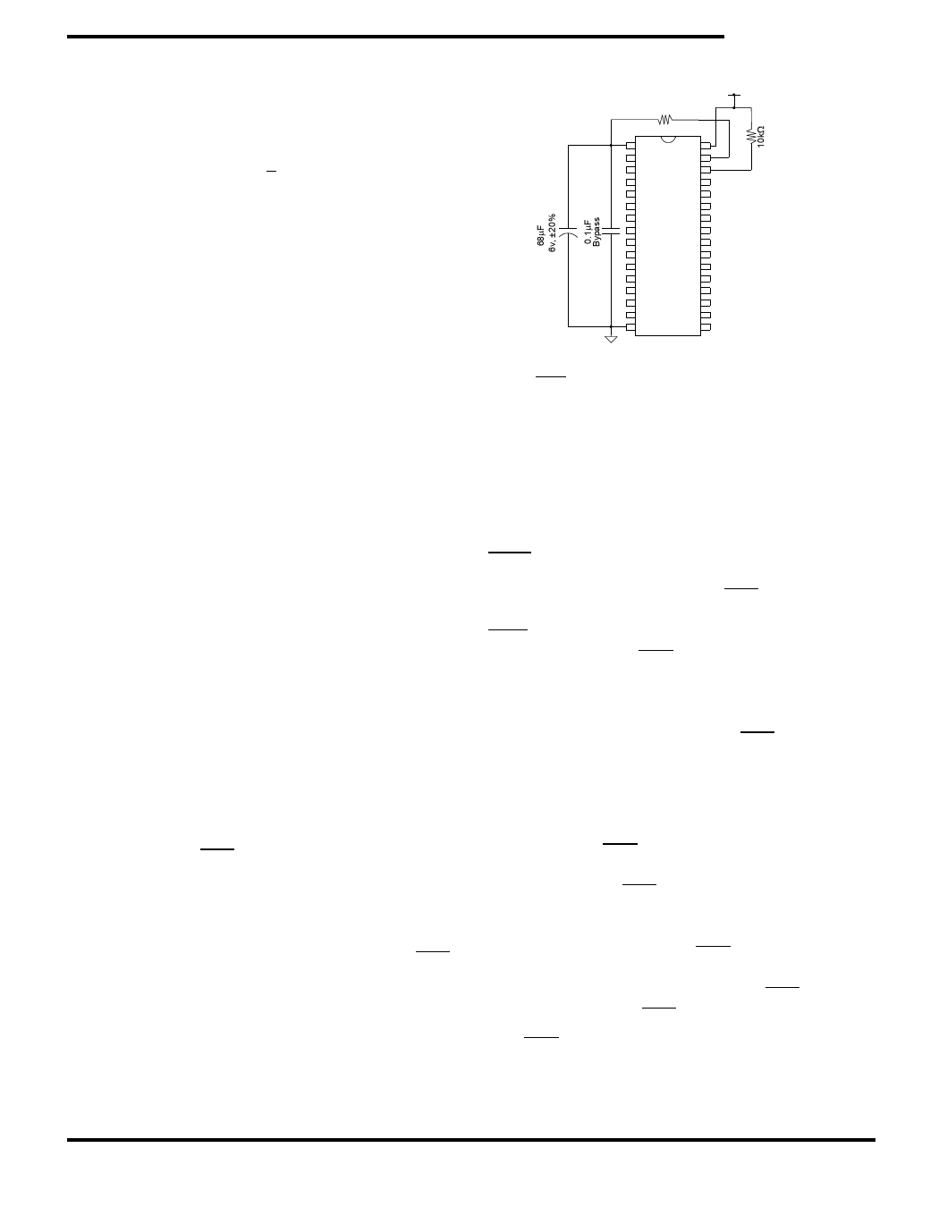
Figure 2 shows the proper connection of capacitors
for automatic store operation. A charge storage
capacitor having a capacity of between 68µF and
220µF (± 20%) rated at 4.7V should be provided.
In order to prevent unneeded STORE operations,
automatic STOREs as well as those initiated by
externally driving HSB low, will be ignored unless at
least one WRITE operation has taken place since the
most recent STORE or RECALL cycle. Software-
initiated STORE cycles are performed regardless of
whether a WRITE operation has taken place. An
optional pull-up resistor is shown connected to HSB.
This can be used to signal the system that the
AutoStore™ cycle is in progress.
10kΩ∗
1
32
31
30
+
16
17
Figure 2: AutoStore™ Mode
*If HSB is not used, it should be left unconnected.
If the power supply drops faster than 20 µs/volt
before VCCX reaches VSWITCH, then a 1 ohm resistor
should be inserted between VCCX and the system
supply to avoid a momentary excess of current
between Vccx and Vcap.
HSB OPERATION
The STK14C88-3 provides the HSB pin for control-
ling and acknowledging the STORE operations. The
HSB pin can be used to request a hardware STORE
cycle. When the HSB pin is driven low, the
STK14C88-3 will conditionally initiate a STORE oper-
ation after tDELAY; an actual STORE cycle will only
begin if a WRITE to the SRAM took place since the
last STORE or RECALL cycle. The HSB pin also acts
as an open drain driver that is internally driven low
to indicate a busy condition while the STORE (initi-
ated by any means) is in progress.
SRAM READ and WRITE operations that are in
progress when HSB is driven low by any means are
given time to complete before the STORE operation
is initiated. After HSB goes low, the STK14C88-3
will continue SRAM operations for tDELAY. During tDELAY,
multiple SRAM READ operations may take place. If a
WRITE is in progress when HSB is pulled low it will
be allowed a time, tDELAY, to complete. However, any
SRAM WRITE cycles requested after HSB goes low
will be inhibited until HSB returns high.
The HSB pin can be used to synchronize multiple
STK14C88-3s while using a single larger capacitor.
November 2003
9 Document Control # ML0015 rev 0.3
Share Link: 