CXD2559 Ver la hoja de datos (PDF) - Intersil
Número de pieza
componentes Descripción
Fabricante
CXD2559 Datasheet PDF : 11 Pages
| |||
HI2559, CXD2559
CONTROL
BIT
CONTROL
WHEN SYSTEM IS CLEARED
L7 TO L0
The L channel attenuation data.
FF (H)
R7 to R0
The R channel attenuation data.
FF (H)
P3 to P0
Output selection.
9 (H) Stereo
E
De-emphasis (High = on, Low = off)
OFF
However, the time constant of the emphasis is γ 1 = 50µs and γ 2 = 15µs
when FS = 44.1kHz. The de-emphasis function cannot be used when FS
is not 44.1kHz.
A
Attenuate (Low = independent, High = common). However, the L channel Independent
attenuation value is used when the L and R channels are commonly atten-
uated.
X
Don’t care.
NOTE: When the data is more than three bytes are transferred to the ATT pin, only the three bytes transferred finally are effective.
D. Digital Attenuator
[Related pins] ATT, SHIFT, LATCH
The output data can be attenuated independently in the L
and R channels, using the transfer data from the external
microcomputer.
The ATT data of the L and R channels consist of eight bits
each, and the L and R channels can be attenuated com-
monly using the ATT control bit. (The L channel attenuation
value is used when the L and R channels are commonly
attenuated).
(1) Command and Audio Output
The attenuation data of the L and R channels consist of eight
bits, it can be set 255 ways. The following table shows the
relationship between the commands and the outputs.
(FS = 44kHz for CD).
0dB
A
ATT1
B
ATT3
C
ATT2
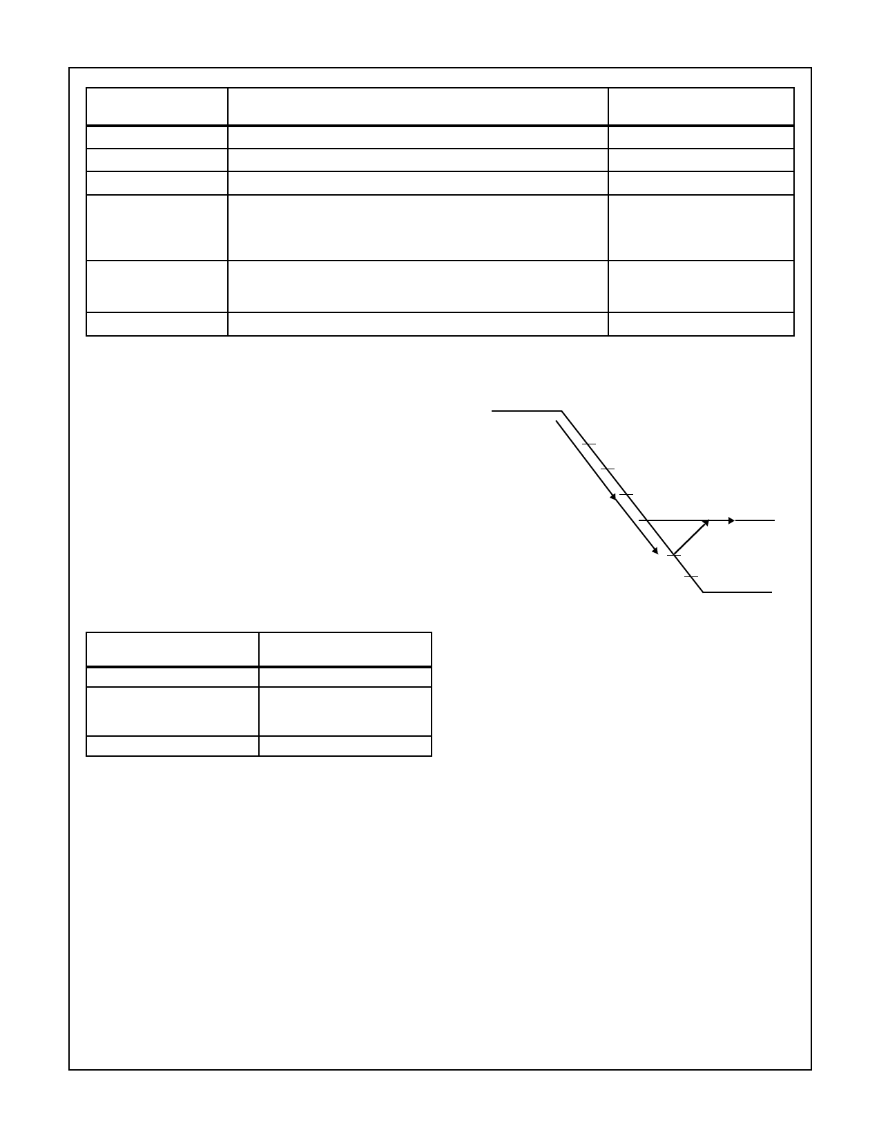
FIGURE 7. METHOD OF OBTAINING AN ATTENUATION VALUE
ATTENUATION DATA
L7 TO L0/R7 TO R0
FF (H)
FE (H)
↓
01 (H)
00 (H)
AUDIO OUTPUT
0dB
-0.034dB
↓
-48.131dB
-∞
F. Output Selection
[Related pins] ATT, SHIFT, LATCH
The L and R channel outputs can be set in four combinations
[L/RL + R/Mute] (16 ways in total) using the transfer data
from the external microcomputer. The following table shows
the relationship between the commands and the outputs.
The attenuation values for 01 (H) to FE (H) can be obtained
with the following equation:
ATT = 20log [Input data/255] dB
Ex. for attenuating data FA (H)
ATT = 20log [250/255] db = 0.172dB
E. Digital Attenuator
Suppose that there are attenuation data ATT1, ATT2 and
ATT3, and their relationship is ATT1>ATT3>ATT2. When
ATT2 is transferred before the level reaches the value of
ATT1 (point A in the figure), the level keeps approaching to
the value of ATT2. Next, when ATT3 is transferred before
the level reaches the value of ATT2 (point B or C in the fig-
ure), the level starts approaching to the value of ATT3 from
its level at that time (point B or C in the figure). The transition
(0 dB to → –∞) between the attenuation data is 1024/FS
4-9
Share Link: 