CMX869P4 Ver la hoja de datos (PDF) - CML Microsystems Plc
Número de pieza
componentes Descripción
Fabricante
CMX869P4 Datasheet PDF : 46 Pages
| |||
Low Power V.32 bis Modem
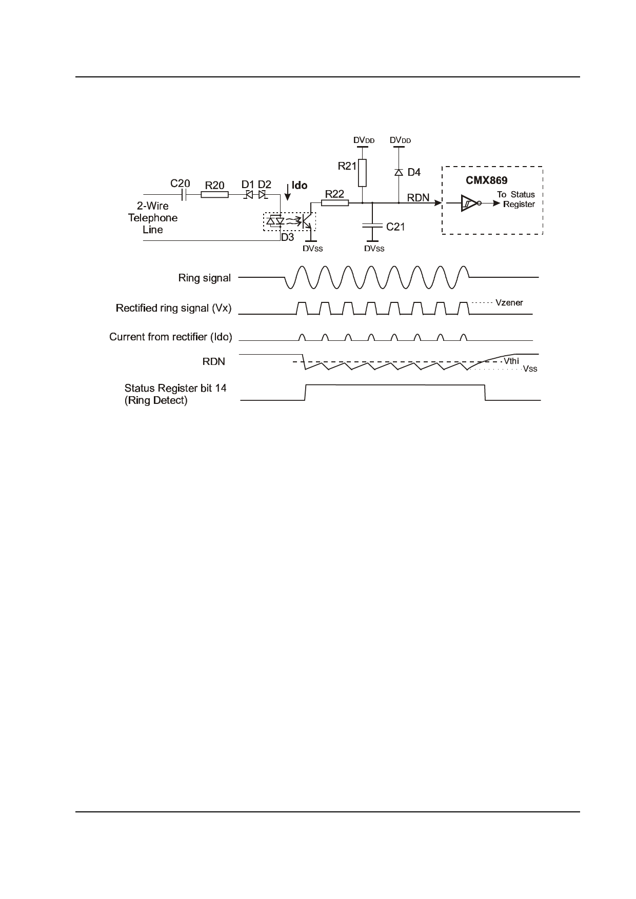
4.2 Ring Detector Interface
CMX869
R20
10kΩ, 0.5W
R21
470kΩ
R22
100Ω
C20
0.33µF, 250V
C21
D1, D2
D3
D4
0.33µF
18V zener
Opto isolator (NEC PS2701-1)
1N4004
Resistors ±5%, capacitors ±20%. Circuit and all component types and values TBD.
Figure 3 Ring Signal Detector Interface Circuit
Figure 3 shows how the CMX869 may be used to detect the large amplitude Ringing signal voltage
present on the 2-wire line at the start of an incoming telephone call. The ring signal is usually applied at
the subscriber's exchange as an ac voltage inserted in series with one of the telephone wires and will
pass through C20, R20, D1 and D2, and appear at the terminals of D3. When the signal reaches the
zeners’ (D1, D2) turn-on voltage, current will flow into the opto-isolator diode, turning on its output
transistor and discharging capacitor C21. Resistor R22 limits the current drawn by the opto-isolator output
to ~30mA peak (TBD). Whilst the ring tone is active and exceeds the zener voltage, the RDN node will
be taken low and the output of the Schmitt trigger will go high. The state of bit 14 (Ring Detect) of the
Status Register directly corresponds to the state of the Ring Detect Schmitt trigger output. If the
corresponding interrupt mask bit is set to 1, a C-BUS interrupt will be initiated (see the Status Register
description in section 6.8).
The minimum amplitude ringing signal that is certain to be detected is: Vzener + 2xVdiode + 2V (TBD).
© 2003 CML Microsystems Plc
8
D/869/1
Share Link: 