CFULA455KB2A-B0 Ver la hoja de datos (PDF) - Murata Manufacturing
NГәmero de pieza
componentes DescripciГіn
Fabricante
CFULA455KB2A-B0
Murata Manufacturing

CFULA455KB2A-B0 Datasheet PDF : 16 Pages
| |||
!Note вҖўPPleleaasseerreeaaddrraatitninggaanndd!!CCAAUUTTIOIONN((foforrsstotorraaggeeaannddooppeerraatitningg,,rraatitningg,,ssooldldeerrininggaannddmmoouunntitningg,,hhaannddlilningg))ininththisisPcDatFalcoagtatolopgrteovepnretvsemnot ksimngokaindg/oarndb/uorrnbinugr,neintgc., etc.
P05E11.pdf 02.9.2
вҖўTThhisisccaatatalologghhaassoonnlylytytyppicicaal lssppeeccififciacatiotionns.sTbheecraeufosree,thyeorue aisrenroesqpuaecsetefdortodaeptapilreodvespoeucripficroadtiuocntss.pTehceifriecafotiroen, polretaosteraanpsparcotvteheouarpprodvaulcst hsepetcfifoicraptrionduocrt tsrapnescaificctatihoen abpepfororevaolrdsehreinegt .for product specification before ordering.
Ceramic Filters (CERAFILr)/Ceramic Discriminators for Communications Equipment
CERAFILr Plastic Case Miniaturized Type CFWLA_A Series
Ceramic filter CFWLA_A series are low profile high
selectivity ceramic filters which use 6 elements in
ladder form.
They are best suitable to high-class transceivers,
cordless telephones and amateur radios.
s Features
1. Low profile, high selectivity.
2. Available bandwidths are B to J as standard.
3. Easily mountable on any PC board.
4. Operating temperature range : -20 to +80 (degree C)
Storage temperature range : -40 to +85 (degree C)
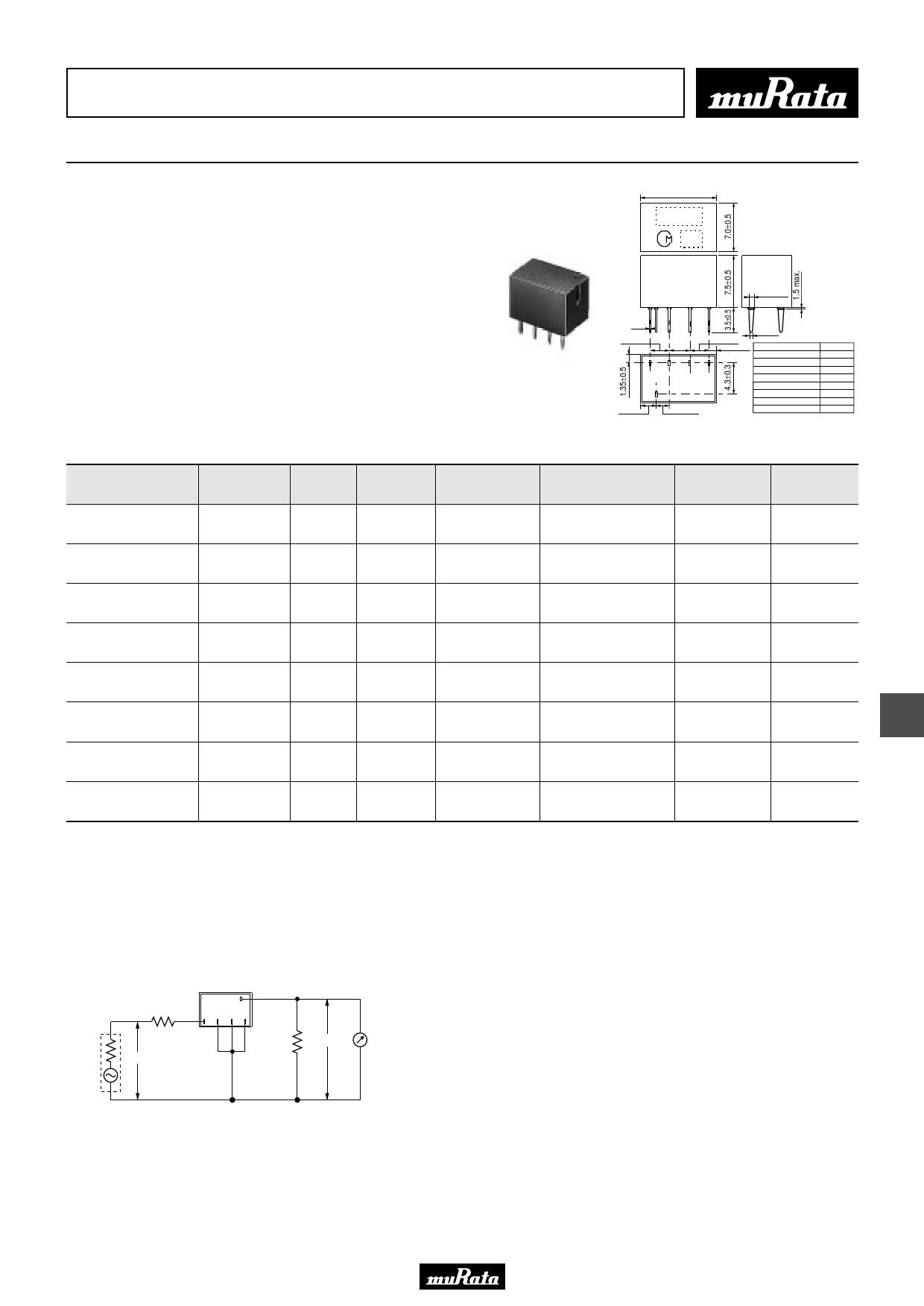
11.0Вұ0.5
MARKING
EIAJ
CODE
0.15
2.9Вұ0.3
2.9вҖ”Вұ00.3.3
2.6Вұ0.3
1.2Вұ0.5
(4) (3) (2) (1)
(5)
2.3Вұ0.5
2.0Вұ0.3
0.8Вұ0.1
Connection
(1) : Input
}(2)
(3) : Ground
(4)
(5) : Output
0.6Вұ0.1
(in mm)
Type
CFWLA455KBFA-B0
CFWLA455KCFA-B0
CFWLA455KDFA-B0
CFWLA455KEFA-B0
CFWLA455KFFA-B0
CFWLA455KGFA-B0
CFWLA455KHFA-B0
CFWLA455KJFA-B0
Marking
B
C
D
E
F
G
HT
IT
Part Number
CFWLA455KBFA-B0
Nominal Center 6dB
Stop
Frequency (fn) Bandwidth Bandwidth
(kHz)
(kHz)
(kHz)
Stop Band
Attenuation
(dB)
Insertion
Loss
(dB)
Ripple
(dB)
455
fnВұ15.0 fnВұ30.0 max.
35 min.
4.0 max.
3.0 max.
min. [within 50dB] [within fnВұ100kHz] [at minimum loss point] [within fnВұ10kHz]
Input/Output
Impedance
(ohm)
1500
CFWLA455KCFA-B0
455
fnВұ12.5 fnВұ24.0 max.
35 min.
4.0 max.
3.0 max.
min. [within 50dB] [within fnВұ100kHz] [at minimum loss point] [within fnВұ8kHz]
1500
CFWLA455KDFA-B0
455
fnВұ10.0 fnВұ20.0 max.
35 min.
4.0 max.
3.0 max.
min. [within 50dB] [within fnВұ100kHz] [at minimum loss point] [within fnВұ7kHz]
1500
CFWLA455KEFA-B0
455
fnВұ7.5
min.
fnВұ15.0 max.
35 min.
6.0 max.
3.0 max.
[within 50dB] [within fnВұ100kHz] [at minimum loss point] [within fnВұ5kHz]
1500
CFWLA455KFFA-B0
455
fnВұ6.0
min.
fnВұ12.5 max.
35 min.
6.0 max.
3.0 max.
[within 50dB] [within fnВұ100kHz] [at minimum loss point] [within fnВұ4kHz]
2000
CFWLA455KGFA-B0
455
fnВұ4.5
min.
fnВұ10.0 max.
35 min.
6.0 max.
2.0 max.
[within 50dB] [within fnВұ100kHz] [at minimum loss point] [within fnВұ3kHz]
2000
CFWLA455KHFA-B0
455
fnВұ3.0
min.
fnВұ9.0 max.
60 min.
6.0 max.
2.0 max.
[within 50dB] [within fnВұ100kHz] [at minimum loss point] [within fnВұ2kHz]
2000
CFWLA455KJFA-B0
455
fnВұ2.0
min.
fnВұ7.5 max.
60 min.
7.0 max.
2.0 max.
[within 50dB] [within fnВұ100kHz] [at minimum loss point] [within fnВұ1.5kHz]
2000
For safety purposes, connect the output of filters to the IF amplifier through a D.C. blocking capacitor. Avoid applying a direct current to the output of ceramic filters.
The order quantity should be an integral multiple of the "Minimum Quantity" shown in package page in this catalog.
11
s Test Circuit
Rg
S.S.G.
0dBm
(5)
R1
(1) (2) (3) (4)
R2
E2
E1
RF Voltmeter
Connection
(1) : Input
(5) : Output
(2)(3)(4) : Ground
Rg+R1=R2=Input/Output Impedance
33
Share Link: