CA3078M Ver la hoja de datos (PDF) - Intersil
Número de pieza
componentes Descripción
Fabricante
CA3078M Datasheet PDF : 12 Pages
| |||
CA3078, CA3078A
TABLE 1. UNITY GAIN SLEW RATE vs COMPENSATION - CA3078 AND CA3078A
VSUPPLY = ±6V, Output Voltage (VO) = ±5V, Load Resistance (RL) = 10kΩ, Transient Response: 10% overshoot for an output voltage of 100mV,
Ambient Temperature (TA) = 25oC
UNITY GAIN (INVERTING)
FIGURE 1
UNITY GAIN (NON-INVERTING)
FIGURE 2
COMPENSATION
TECHNIQUE
R1
C1
R2
C2
SLEW RATE
R1
C1
R2
C2 SLEW RATE
kΩ
pF
kΩ
µF
V/µs
kΩ
pF
kΩ
µF
V/µs
CA3078 - IQ = 100µA
Single Capacitor
0
750
∞
0
0.0085
0
1500
∞
0
0.0095
Resistor and Capacitor
3.5
350
∞
0
0.04
5.3
500
∞
0
0.024
Input
∞
0
0.25 0.306
0.67
∞
0
0.311 0.45
0.67
CA3078A - IQ = 20µA
Single Capacitor
0
300
∞
0
0.0095
0
800
∞
0
0.003
Resistor and Capacitor
14
100
∞
0
0.027
34
125
∞
0
0.02
Input
∞
0
0.644 0.156
0.29
∞
0
0.77
0.4
0.4
Application Information
Compensation Techniques
The CA3078A and CA3078 can be phase compensated with
one or two external components depending upon the closed
loop gain, power consumption, and speed desired. The
recommended compensation is a resistor in series with a
capacitor connected from Terminal 1 to Terminal 8. Values of
the resistor and capacitor required for compensation as a
function of closed loop gain are shown in Figures 25 and 26.
These curves represent the compensation necessary at
quiescent currents of 100µA and 20µA, respectively, for a
transient response with 10% overshoot. Figures 23 and 24
show the slew rates that can be obtained with the two different
compensation techniques. Higher speeds can be achieved
with input compensation, but this increases noise output.
Compensation can also be accomplished with a single
capacitor connected from Terminal 1 to Terminal 8, with speed
being sacrificed for simplicity. Table 1 gives an indication of
slew rates that can be obtained with various compensation
techniques at quiescent currents of 100µA and 20µA.
Single Supply Operation
The CA3078A and CA3078 can operate from a single supply
with a minimum total supply voltage of 1.5V. Figures 4 and 5
show the CA3078A or CA3078 in inverting and non-inverting
20dB amplifier configurations utilizing a 1.5V type “AA” cell
for a supply. The total consumption for either circuit is
approximately 675nW. The output voltage swing in this
configuration is 300mVP-P with a 20kΩ load.
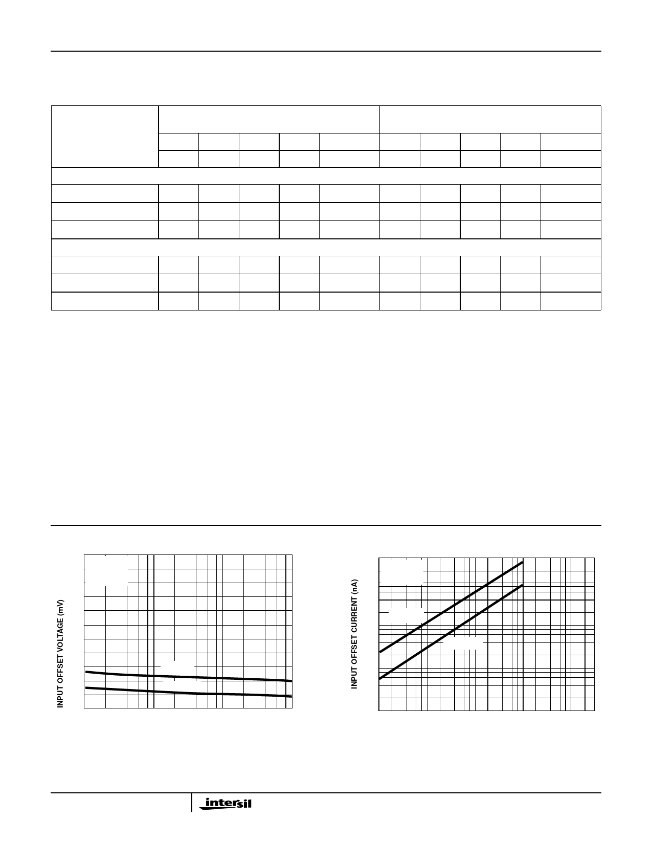
Typical Performance Curves
VS = ±6
TA = 25oC
RS ≤ 10kΩ
VS = ±6
10 TA = 25oC
3.0
2.4
1.8
1.2
0.6
0
1
CA3078
CA3078A
10
100
TOTAL QUIESCENT CURRENT (µA)
1000
FIGURE 6. INPUT OFFSET VOLTAGE vs TOTAL QUIESCENT
CURRENT
CA3078
1
0.1
CA3078A
0.01
1
10
100
1000
TOTAL QUIESCENT CURRENT (µA)
10000
FIGURE 7. INPUT OFFSET CURRENT vs TOTAL QUIESCENT
CURRENT
5
Share Link: 