BYT87-1000 Ver la hoja de datos (PDF) - Vishay Semiconductors
Número de pieza
componentes Descripción
Fabricante
BYT87-1000 Datasheet PDF : 4 Pages
| |||
BYT87
Vishay Telefunken
Electrical Characteristics
Tj = 25_C
Parameter
Forward voltage
Reverse current
Forward recovery time
Turn on transient peak voltage
Reverse recovery
characteristics
Reverse recovery time
Test Conditions
IF=15A
IF=15A, Tj=100°C
VR=VRRM
x VR=VRRM, Tj=100°C
IF=15A, diF/dt 50A/ms
IF=15A, diF/dt=–100A/ms,
VBatt=200V
IF=15A, diF/dt=–100A/ms,
VBatt=200V
IF=0.5A, IR=1A, iR=0.25A
Type Symbol Min Typ Max Unit
VF
1.8 V
VF
1.8 V
IR
10 mA
IR
0.4 mA
tfr
350
ns
VFP
7
V
IRM
10.5
A
tIRM
110
ns
trr
150
ns
trr
80 ns
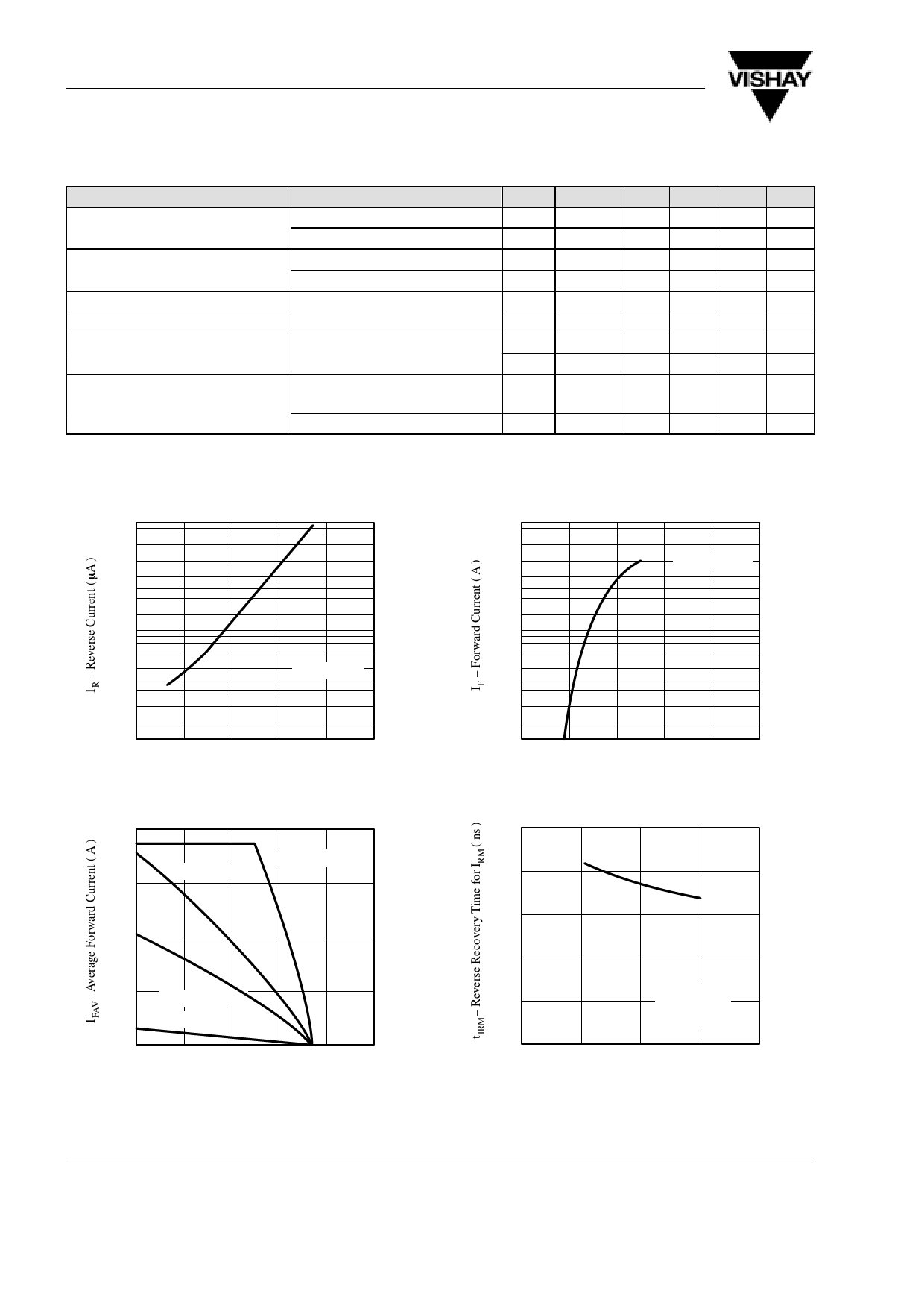
Characteristics (Tj = 25_C unless otherwise specified)
1000
100
100
10
TCase= 25°C
10
1
VR = VR RM
1
0.1
0.1
0
40
80
120 160 200
94 9487
Tj – Junction Temperature ( °C )
Figure 1. Typ. Reverse Current vs. Junction Temperature
16
RthJC=1.6K/W
12
RthJA=5K/W
8
4
RthJA=10K/W
RthJA=85K/W
0
0
40
80
120 160 200
94 9488
Tamb – Ambient Temperature ( °C )
Figure 2. Max. Average Forward Current vs.
Ambient Temperature
0.01
0
0.6
1.2
1.8
2.4 3.0
94 9489
VF – Forward Voltage ( V )
Figure 3. Typ. Forward Current vs. Forward Voltage
150
120
90
60
30
0
0
IF = 15A
TC=25°C
VBatt=200V
50
100
150
200
94 9490 –dIF/dt – Forward Current Rate of Change ( A/ms )
Figure 4. Reverse Recovery Time for IRM vs.
Forward Current Rate of Change
www.vishay.de • FaxBack +1-408-970-5600
2 (4)
Document Number 86038
Rev. 2, 24-Jun-98
Share Link: 