BD8381EFV-M Ver la hoja de datos (PDF) - ROHM Semiconductor
Número de pieza
componentes Descripción
Fabricante
BD8381EFV-M Datasheet PDF : 21 Pages
| |||
BD8381EFV-M
Technical Note
●5V voltage reference (VREG)
5V (Typ.) is generated from the VCC input voltage when the enable pin is set high. This voltage is used to power internal
circuitry, as well as the voltage source for device pins that need to be fixed to a logical HIGH.
UVLO protection is integrated into the VREG pin. The voltage regulation circuitry operates uninterrupted for output
voltages higher than 4.5 V (Typ.), but if output voltage drops to 4.3 V (Typ.) or lower, UVLO engages and turns the IC off.
Connect a capacitor (Creg = 10µF Typ.) to the VREG terminal for phase compensation. Operation may become unstable if
Creg is not connected.
●About the method of setting the output current
ILED=min[THM / 5 V , 0.2V] / RISET [A]
As for min[THM / 5 V, 0.2V], small one is selected from among THM and VFB=0.2V.
Please input within the range of 0.25-5.0V when controlling the output current with THM. Please connect with VREG when
not using THM. There is a possibility that the LED GND short detection malfunctions when THM≦0.25V.
As for PWM brightness, the control by the PWM signal from the outside and brightness with the CR timer are possible.
(GND short protection detection timer (SCP) works at the same time as turning on EN when PWM brightness from the
outside is used. Therefore, there is a possibility of mis-detecting SCP for the time from the EN turning on to the PWM
turning on > GND short protection detection timer.)
VTH
Rcr1
Rcr2
Ccr
20 kΩ
10 kΩ
100000 pF
OUTL
ILED
1.44
FPWM=
(RCR1+2RCR2)CCR
TON_PWM=
RCR2
(RCR1+2RCR2)
×100
Fig. 12
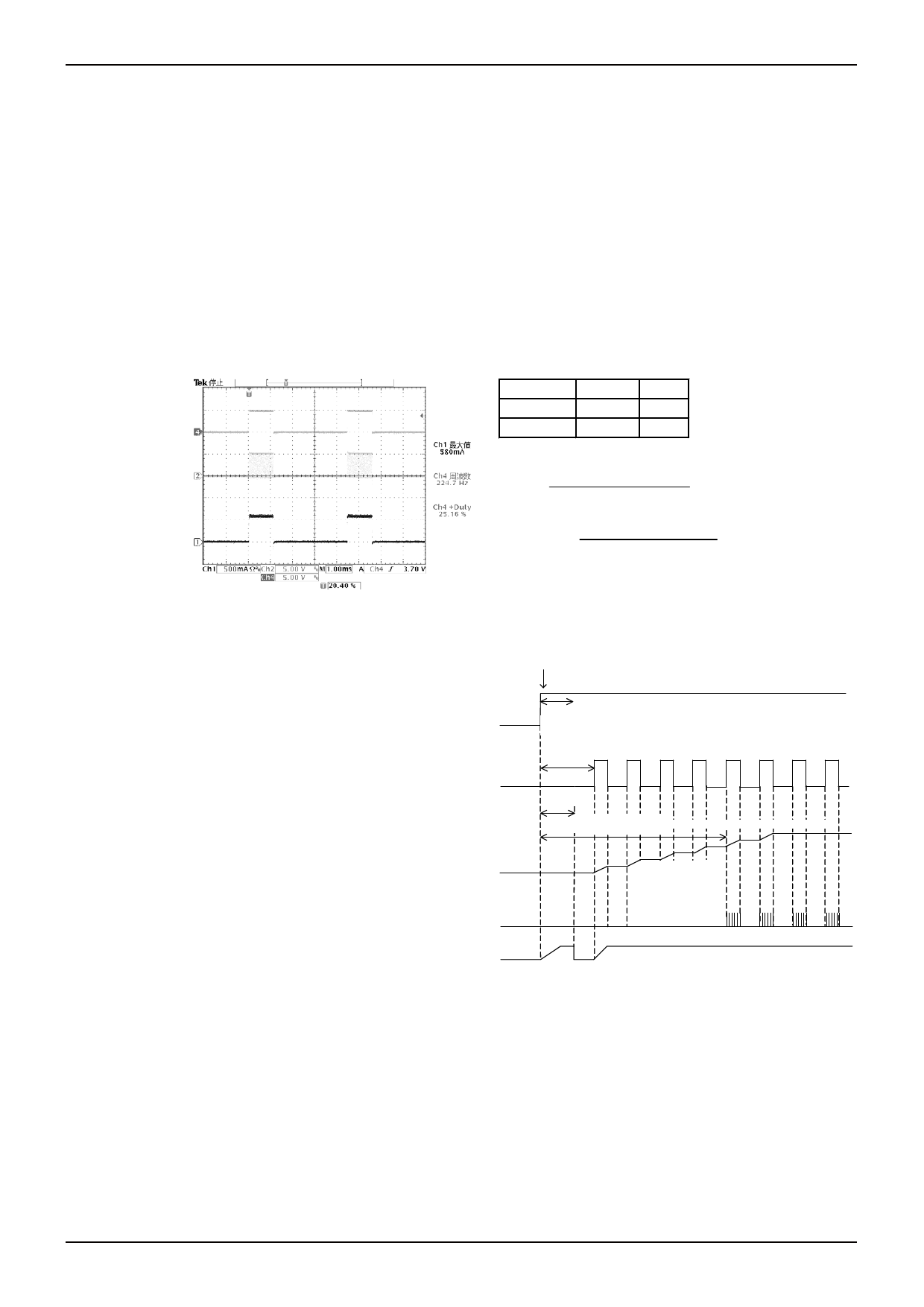
●About time from EN turning on to PWM turning on and the start from PWM low Duty
※The GND short protection detecting function (hereafter,
SCP) starts with EN=Low→Hi, and after the time of the
①SCP timer detection starts
timer set with the external capacitor connected with CT, it
becomes latch off. (Above figure ① and ②)
EN
The charge with SS begins synchronizing with turning on
②Time of SCP timer
EN. The PWM latch off function is built into when there is
not PWM turning on, and when the PWM latch off is
③Time until turning on PWM
detected, (② of SS and the SCP counter) is reset. (The PWM
time of the timer at latch OFF is calculated by oscillatory
frequency ×32770 counts of DC/DC. ) Therefore, the
following relations exist at time until PWM is turned on,
④Time of PWM latch timer ⑤Time until switching starts after inputting PWM
time of PWM latch timer and SCP detection time after EN
is turned on at external brightness.
COUP
(However, after ③ is turned on, ③ <④ is deleted from
the sequence because ④ doesn't operate. )
Each sequence
OUTL
②<④<③⇒SCP is detected and No LED light.
④<②<③⇒LED lighting
SS
④<③<②⇒LED lighting
●About Dirating of the LED current that uses THM
It is an ability to set the Dirating curve of the LED current to the temperature as one of the functions to use THM. As for LED,
because deterioration at the high temperature is fast, the maximum allowance LED currents and the curve of temperatures
is given to the data sheet of LED. The voltage with a negative temperature characteristic in THM the Thermistor resistance
is used is input, and the LED current is controlled when the LED current is controlled according to the temperature
characteristic. Moreover, external Tr is used, and two input composition is also possible.
www.rohm.com
© 2011 ROHM Co., Ltd. All rights reserved.
5/20
2011.04 - Rev.A
Share Link: 