BA5961FV Ver la hoja de datos (PDF) - ROHM Semiconductor
Número de pieza
componentes Descripción
Fabricante
BA5961FV Datasheet PDF : 7 Pages
| |||
Optical disc ICs
BA5961FV
!Operation notes
1. A thermal-shutdown circuit (over-temperature protection circuit) is built in to prevent the IC from thermal breakdown.
Use the IC under the thermal loss allowed to the package. In case the IC is left running over the allowable loss, the
junction temperature rises, and the thermal-shutdown circuit works at the junction temperature of 175°C (typ.)
(the outputs of the driver is turned off). When the junction temperature drops to 150°C (typ.), the IC start operating
again.
2. When stand-by control terminal (Pin 10) drops below 0.5V, stand-by mode is established. Make sure that under normal
operating conditions, this pin at 2.0V or above.
3. If PreVCC (Pin 9) drops below 3.4V (typ.), the driver is turned off. When the voltage exceeds 3.6V (typ.) the driver
returns to its previous state.
4. If the bias pin (Pin 20) drops below 0.7V, the output is muted. Make sure that under normal operating conditions, this
pin is at 1.0V or above.
5. The output is muted in the event of a thermal shut down, mute-on, or a bias and Pre-VCC voltage drop. Only the driver
is muted. When muted, the internal bias voltage of the output pin becomes roughly (Pow VCC-Vf) / 2).
6. Please connect a bypass capacitor (0.1µF) across the supply voltage lines close to the IC pins.
7. When a capacitance load is connected to the OP amplifier output, the amplifier phase margin decreases, which causes
the peak or oscillation. When connecting such load, insert a resistance in series between the output and the
capacitance load and take a full consideration for frequency characteristics to prevent problem during practical use.
8. Do not short-circuit between any output pin and supply pin (supply fault) or ground (ground fault), or between any
output pins (load short-circuit). When mounting the IC on the circuit board, be extremely cautions about the orientation
of the IC. If the orientation is mistaken, the IC may break down, and produce smoke in some cases.
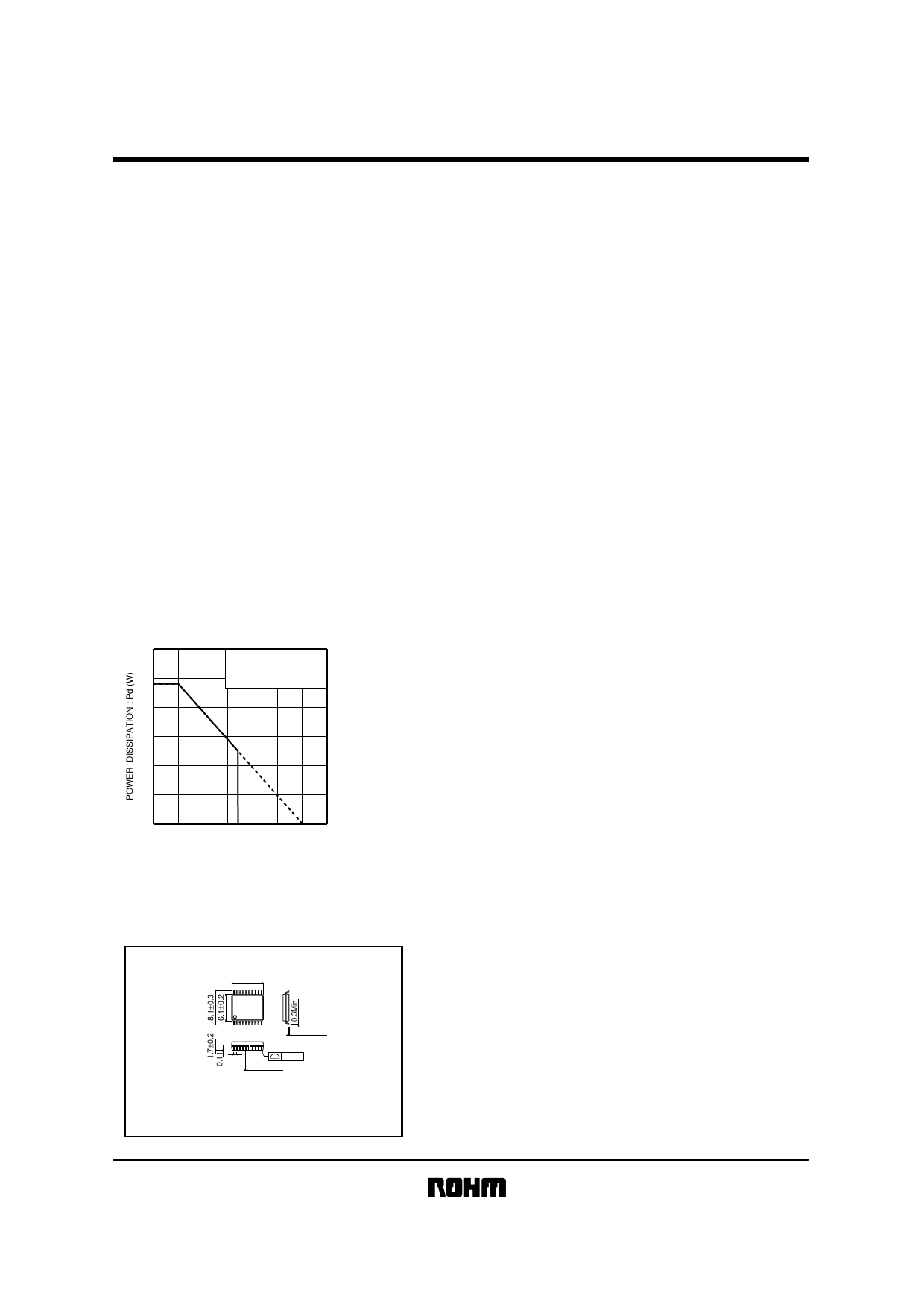
!Electrical characteristics curve
1.5
On less than 3%
(percentage occupied by copper foil),
70mm×70mm, t=1.6mm
glass epoxy mounting.
1.0
0.5
0
0 25 50 75 100 125 150 175
AMBIENT TEMPERATURE : Ta (°C)
Fig.3 Power dissipation
!External dimensions (Units : mm)
6.5±0.2
20
11
1
10
0.15±0.1
0.65
0.1
0.22±0.1
SSOP-B20W
7/7
Share Link: 