BA3528 Ver la hoja de datos (PDF) - ROHM Semiconductor
Número de pieza
componentes Descripción
Fabricante
BA3528 Datasheet PDF : 14 Pages
| |||
Audio ICs
BA3528AFP / BA3529AFP
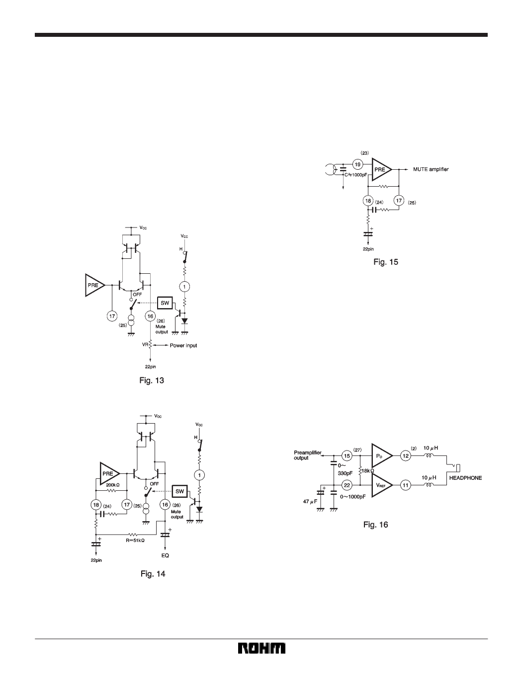
(4) Mute amplifier output
To switch the mute amplifier on and off, switch the
constant-current supply for the mute amplifier off and on
by switching the voltage on pin 1 (Pre-mute SW) high or
low. When the mute is switched on, the mute amplifier
output goes open circuit and the output voltage is unsta-
ble resulting in the generation of an audible “pop” sound.
To prevent this, bias pin 22 through the volume control as
shown in Fig. 13.
In applications that use a directly connected output cou-
pling capacitor, connect a resister as shown in the circuit
diagram in Fig. 14 to reduce the pre-mute switching noise
described in (3) above.
(5) Preventing oscillation
Connect a capacitor of approximately 1000pF between
the preamplifier input and pin 22 to prevent oscillation,
and as a countermeasure against strong electric fields.
This capacitor can also be used for treble-region com-
pensation. In this case, decide on a value for it based on
the relationship with the impedance of the magnetic head
(see Fig. 15).
When countermeasures against strong electric fields for
the power amplifiers are required, connect bypass ca-
pacitors between each input pin and pin 22, and connect
choke coils in series with the output pins and the head-
phones. The component values should be about 330pF
for the bypass capacitors, and the 10µH for the choke
coils so that they do not effect the audible frequency
range.
Another effective measure is to connect a bypass capaci-
tor of about 1000pF in parallel with the filter capacitor be-
tween pin 22 and ground (pin 21). Refer to the circuit dia-
gram in Fig. 16.
394
Share Link: 