AWT6131 Ver la hoja de datos (PDF) - ANADIGICS
Número de pieza
componentes Descripción
Fabricante
AWT6131 Datasheet PDF : 12 Pages
| |||
AWT6131
APPLICATION INFORMATION
To ensure proper performance, refer to all related
Application Notes on the ANADIGICS web site:
http://www.anadigics.com
Shutdown Mode
The power amplifier may be placed in a shutdown
mode by applying logic low levels (see Operating
Ranges table) to both the VREF and VMODE voltages.
Bias Modes
The power amplifier may be placed in either a Low
Bias mode or a High Bias mode by applying the
appropriate logic level (see Operating Ranges table)
to the VMODE voltage. The Bias Control table lists the
recommended modes of operation for various
applications.
APPLICATION
CDMA - low power
CDMA - high power
Shutdown
Table 5: Bias Control
POUT
LEVELS
BIAS
MODE
VREF
<+16dBm
Low +2.9 V
>+16 dBm
High +2.9 V
-
Shutdown 0 V
VMODE
+2.9 V
0V
0V
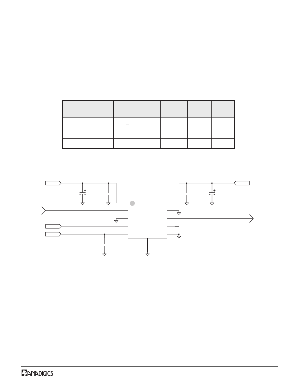
VCC1
C9
10uF tantalum
RF IN
VMODE
VREF
C1
0.01uF
1 VCC
2 RFIN
3 GND
4 VMODE
5 VREF
C2
0.01uF
VCC 10
GND 9
RFOUT 8
GND 7
GND 6
GND
at slug
C4
0.01uF
VCC2
C8
10uF tantalum
RF OUT
Figure 12: Application Circuit Schematic
PRELIMINARY DATA SHEET - Rev 1.0
7
11/2002
Share Link: 