ATF1504BE Ver la hoja de datos (PDF) - Atmel Corporation
Número de pieza
componentes Descripción
Fabricante
ATF1504BE Datasheet PDF : 30 Pages
| |||
ATF1504BE
5.1 In-System Configuration – ISC (Also Referred to as ISP)
This mode is the de-facto standard used to program the CPLD when it is attached to a PCB. The
term ISC can also be used interchangeably with ISP (In-system Programming). ISC or ISP elim-
inates the need for an external device programmer, and the devices can be soldered to a PCB
without being preprogrammed.
In the ISC mode, the logic operation of the ATF1504BE is halted and the embedded configura-
tion memory is programmed. The device is programmed by first erasing the configuration
memory in the CPLD and then loading the new configuration data into the memory, which in-turn
configures the PLD for functional mode. When the device is in the ISC programming mode, all
user I/Os are held in the high impedance state.
The ISC mode is best suited for working with the ATF1504BE device in a design development or
production environment. Configuration of the ATF1504BE device done via a Download Cable
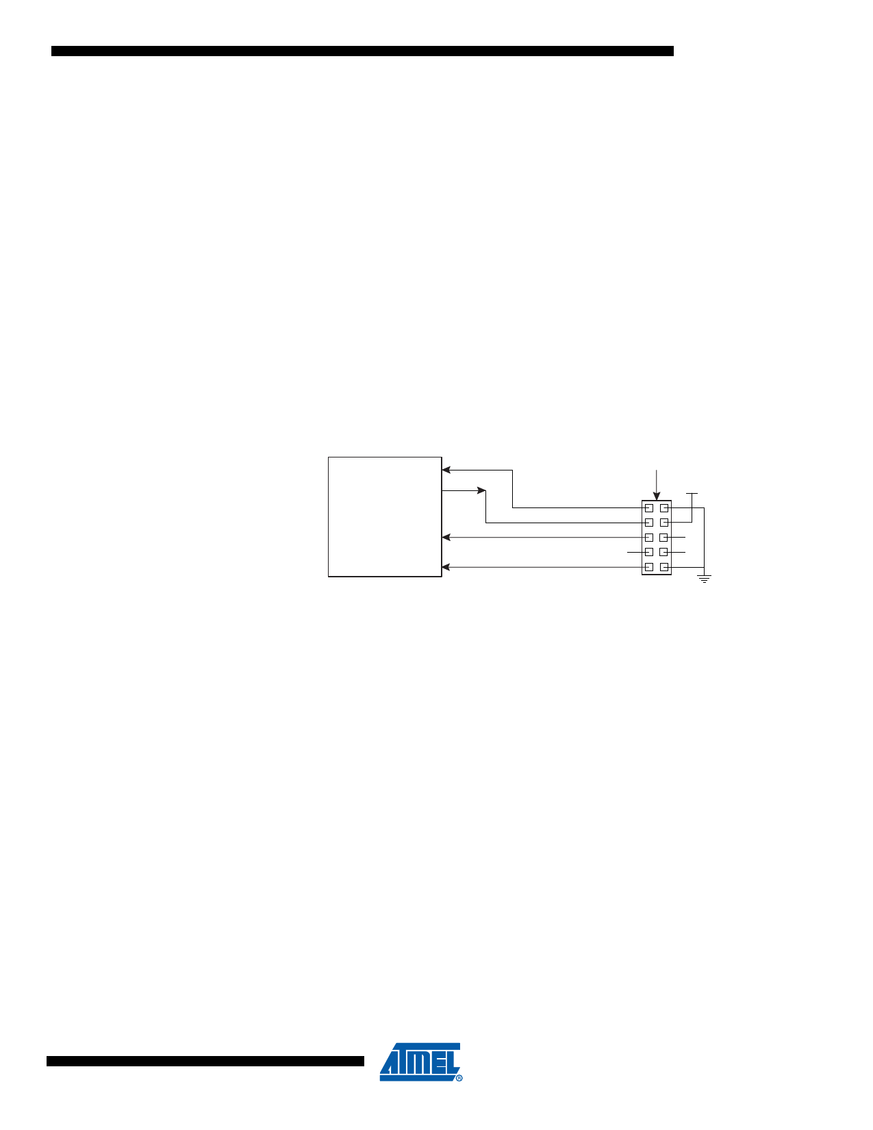
(see Figure 5-1 on page 11) is the default mode used to program the device in the ISC mode. In
this mode, the PC is typically the controlling device that communicates with the CPLD.
Figure 5-1.
Configuration of ATF1504BE Device Using a Download Cable
ATF1504BE
CPLD Device
TCK
TDO
TMS
TDI
Connect
ISP Download
Cable to 10-pin
JTAG Header
VCC
1
2
3
4
5
6
7
8
9
10
JTAG
Connector
5.2 On-the-Fly Reconfiguration – OTF
In this mode, the CPLD design pattern stored in the internal configuration memory can be modi-
fied while the previously-programmed design pattern is operating with minimal disturbance to
the programming operation of the new design. The new configuration will take affect after the
OTF programming process is completed and the OTF mode is exited.
The configuration data for any design is stored in the internal configuration memory. Once the
configuration data is transferred to the internal static registers of the CPLD, the CPLD operates
with the design pattern and the configuration memory is free to be re-loaded with a new set of
configuration data. The design pattern due to the new configuration content is activated through
an initialization cycle that occurs on exiting the OTF mode or after the next power up sequence.
Figure 5-2 shows the electrical interface for configuration of the ATF1504BE device in the OTF
mode. The processor is the controlling device that communicates with the CPLD and uses con-
figuration data stored in the external memory to configure the CPLD.
11
3637B–PLD–1/08
Share Link: 