ATF-34143-TR1G Ver la hoja de datos (PDF) - Avago Technologies
Número de pieza
componentes Descripción
Fabricante
ATF-34143-TR1G Datasheet PDF : 14 Pages
| |||
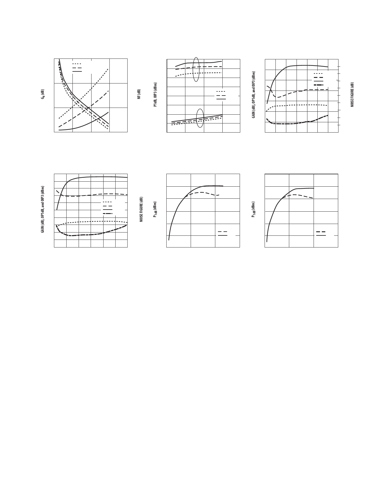
ATF-34143 Typical Performance Curves, continued
25
1.5
85 C
25 C
-40 C
20
1.0
15
0.5
10
0
0
2000
4000
6000 8000
FREQUENCY (GHz)
Figure 14. Fmin and Ga vs. Frequency and Temperature
at VDS = 4 V, IDS = 60 mA.
33
31
29
27
OIP3
85 C
25
25 C
-40 C
23
P1dB
21
19
17
0
2000
4000
6000 8000
FREQUENCY (MHz)
F=ig4uVr,eID1S5=.6P01dmB,AI.P[13]vs. Frequency and Temperature at VDS
35
5.0
4.5
30
Gain
4.0
OP1dB
25
OIP3
3.5
NF
20
3.0
2.5
15
2.0
10
1.5
1.0
5
0.5
0
0
0 20 40 60 80 100 120 140
IDSQ (mA)
Figure 16. NF, Gain, OP1dB and
3.9 GHz Tuned for Noise Figure.
OIP3
[1]
vs.
IDS
at
4
V
and
30
5.0
25
25
27
4.5
24
4.0
20
20
21
3.5
15
15
18
Gain
OP1dB
3.0
15
OIP3
2.5
10
10
NF
12
2.0
9
1.5
5
5
6
1.0
0
3V
4V
0
3V
4V
3
0.5
0
0
0 20 40 60 80 100 120
-5
-5
0
50
100
150
0
50
100
150
IDSQ (mA)
IDS (mA)
IDS (mA)
Figure 17. NF, Gain, OP1dB and OIP3 vs. IDS at 4 V and
5.8 GHz Tuned for Noise Figure.[1]
Figure 18. P1dB vs. IDS Active Bias Tuned for NF @ 4V, 60 Figure 19. P1dB vs. IDS Active Bias Tuned for min NF @
mA at 2 GHz.
4V, 60 mA at 900 MHz.
Note:
1. P1dB measurements are performed with passive biasing. Quicescent drain current, IDSQ, is set with zero RF drive applied. As P1dB is approached,
the drain current may increase or decrease depending on frequency and dc bias point. At lower values of IDSQ the device is running closer to class
B as power output approaches P1dB. This results in higher PAE (power added efficiency) when compared to a device that is driven by a constant
current source as is typically done with active biasing. As an example, at a VDS = 4 V and IDSQ = 10 mA, Id increases to 62 mA as a P1dB of +19 dBm
is approached.
5
Share Link: 