ATA6602 Ver la hoja de datos (PDF) - Atmel Corporation
Número de pieza
componentes Descripción
Fabricante
ATA6602 Datasheet PDF : 362 Pages
| |||
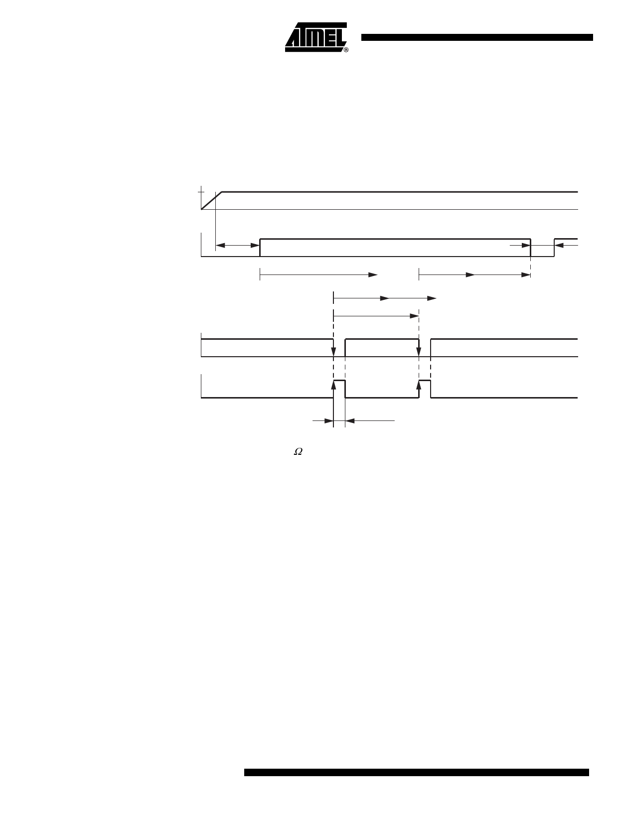
troller after td = 49 ms. The times t1 and t2 have a fixed relationship with each other. A triggering
signal from the microcontroller is anticipated within the time frame of t2 = 10.5 ms. To avoid false
triggering from glitches, the trigger pulse must be longer than ttrigg > 3 µs. This slope serves to
restart the watchdog sequence. Should the triggering signal fail in this open window t2, the
NRES output will be drawn to ground after t2. A triggering signal during the closed window t1
causes NRES to immediately switch low.
Figure 3-9.
VDD = 5V
Timing Sequence with RWD_OSC = 51 kΩ
NRES
Undervoltage Reset
treset = 10 ms
Watchdog Reset
tnres = 1.9 ms
td = 49 ms
t1
t2
t1 = 10 ms t2 = 10.5 ms
twd
NTRIG
PTRIG
ttrigg > 3 µs
3.3.17.2
Worst Case Calculation with RWO_OSC = 51 kΩ
The internal oscillator has a tolerance of ±20%. This means that t1 and t2 can also vary by ±20%.
The worst case calculation for the watchdog period Twd the microcontroller has to provide is
calculated as follows.
The ideal watchdog time Twd is between (t1maximum) and (t1 minimum plus t2 minimum).
t1,min = 0.8 × t1 = 8 ms, t1,max = 1.2 × t1 = 12 ms
t2,min = 0.8 × t2 = 8.4 ms, t2,max = 1.2 × t2 = 12.6 ms
Twdmax = t1min + t2min = 8 ms + 8.4 ms = 16.4 ms
Twdmin = t1max = 12 ms
Twd = 14.2 ms ±2.2 ms (±15%)
A microcontroller with an oscillator tolerance of ±15% is sufficient to supply the trigger inputs
correctly within the time period of Twd = 14.2 ms (±15%) in an application with Rwd_osc = 51 kΩ.
16 ATA6602/ATA6603
4921C–AUTO–01/07
Share Link: 