AT90S1200 Ver la hoja de datos (PDF) - Atmel Corporation
Número de pieza
componentes Descripción
Fabricante
AT90S1200 Datasheet PDF : 71 Pages
| |||
Power-on Reset
0838H–AVR–03/02
AT90S1200
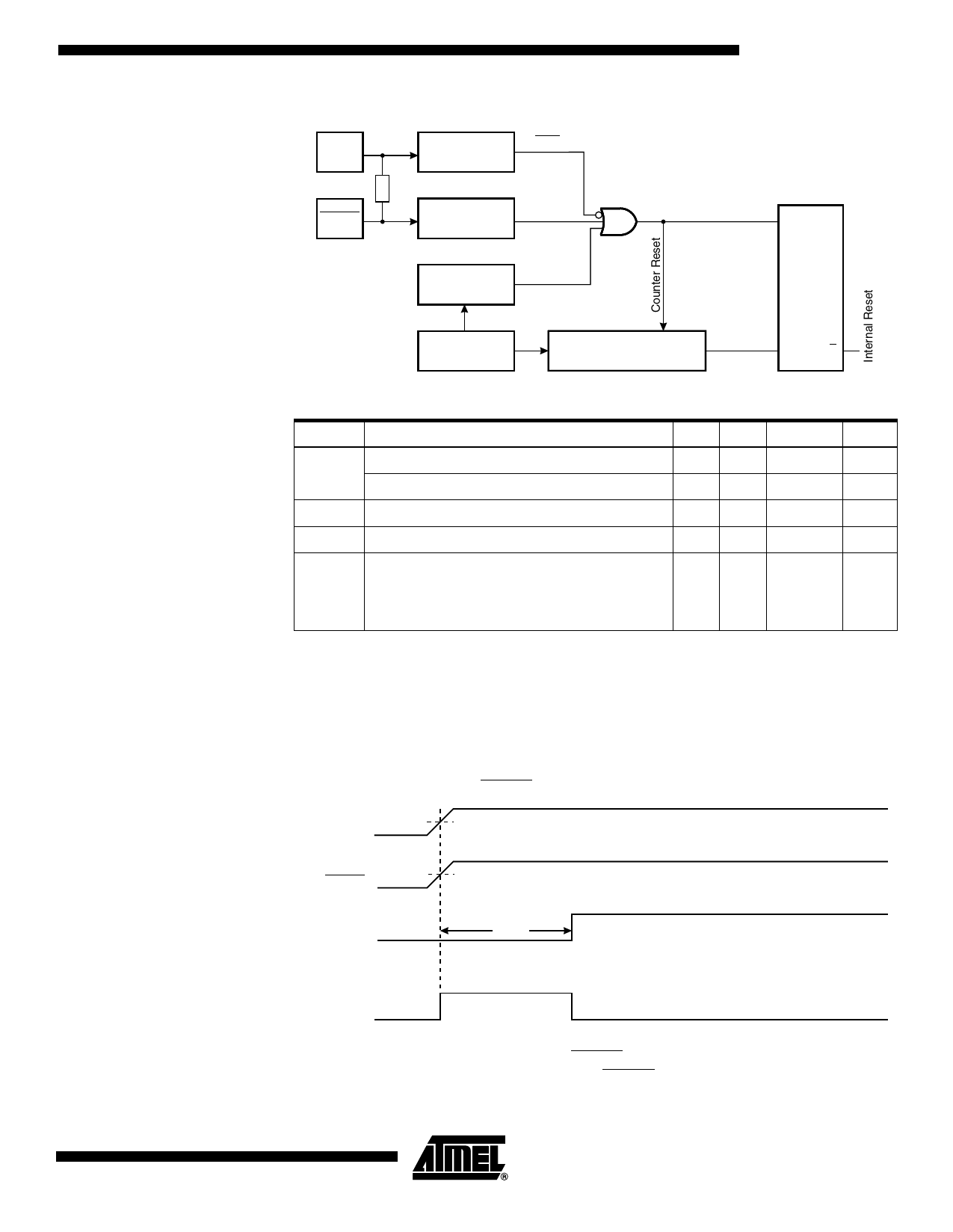
Figure 13. Reset Logic
VCC
Power-on Reset
Circuit
100 - 500K
RESET
Reset Circuit
POR
S
Q
Watchdog
Timer
On-chip
RC Oscillator
14-stage Ripple Counter Time-out R
Q
Table 3. Reset Characteristics (VCC = 5.0V)
Symbol Parameter
Min Typ Max Units
Power-on Reset Threshold Voltage (rising)
0.8 1.2
1.6
V
VPOT(1)
Power-on Reset Threshold Voltage (falling)
0.2 0.4
0.6
V
VRST
Pin Threshold Voltage
–
– 0.85 VCC
V
tPOR
Power-on Reset Period
2.0 3.0
4.0
ms
Reset Delay Time-out Period (The Time-out
tTOUT
period equals 16K WDT cycles. See “Typical
Characteristics” on page 51. for typical WDT
11.0 16.0
21.0
ms
frequency at different voltages).
Note: 1. The Power-on Reset will not work unless the supply voltage has been below VPOT
(falling).
A Power-on Reset (POR) circuit ensures that the device is reset from power-on. As
shown in Figure 13, an internal timer clocked from the Watchdog timer oscillator pre-
vents the MCU from starting until after a certain period after VCC has reached the Power-
on Threshold voltage (VPOT), regardless of the VCC rise time (see Figure 14).
Figure 14. MCU Start-up, RESET Tied to VCC.
VCC
VPOT
RESET
VRST
TIME-OUT
tTOUT
INTERNAL
RESET
If the built-in start-up delay is sufficient, RESET can be connected to VCC directly or via
an external pull-up resistor. By holding the RESET pin low for a period after VCC has
13
Share Link: 