AT89S52-24AC Ver la hoja de datos (PDF) - Atmel Corporation
Número de pieza
componentes Descripción
Fabricante
AT89S52-24AC Datasheet PDF : 39 Pages
| |||
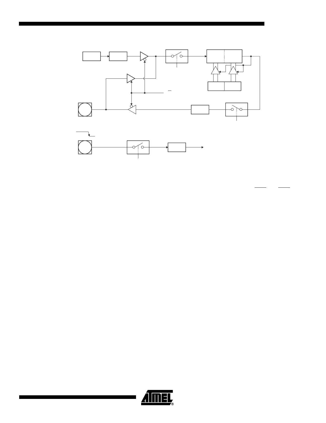
Figure 12-1. Timer 2 in Clock-Out Mode
OSC
÷2
P1.0
(T2)
P1.1
(T2EX)
TRANSITION
DETECTOR
EXEN2
AT89S52
TR2
C/T2 BIT
TL2
TH2
(8-BITS) (8-BITS)
RCAP2L RCAP2H
÷2
T2OE (T2MOD.1)
EXF2
TIMER 2
INTERRUPT
13. Interrupts
The AT89S52 has a total of six interrupt vectors: two external interrupts (INT0 and INT1), three
timer interrupts (Timers 0, 1, and 2), and the serial port interrupt. These interrupts are all shown
in Figure 13-1.
Each of these interrupt sources can be individually enabled or disabled by setting or clearing a
bit in Special Function Register IE. IE also contains a global disable bit, EA, which disables all
interrupts at once.
Note that Table 13-1 shows that bit position IE.6 is unimplemented. User software should not
write a 1 to this bit position, since it may be used in future AT89 products.
Timer 2 interrupt is generated by the logical OR of bits TF2 and EXF2 in register T2CON. Nei-
ther of these flags is cleared by hardware when the service routine is vectored to. In fact, the
service routine may have to determine whether it was TF2 or EXF2 that generated the interrupt,
and that bit will have to be cleared in software.
The Timer 0 and Timer 1 flags, TF0 and TF1, are set at S5P2 of the cycle in which the timers
overflow. The values are then polled by the circuitry in the next cycle. However, the Timer 2 flag,
TF2, is set at S2P2 and is polled in the same cycle in which the timer overflows.
17
1919C–MICRO–3/05
Share Link: 