AT17C010 Ver la hoja de datos (PDF) - Atmel Corporation
Número de pieza
componentes Descripción
Fabricante
AT17C010 Datasheet PDF : 13 Pages
| |||
AT17C512/010/LV512/010
.
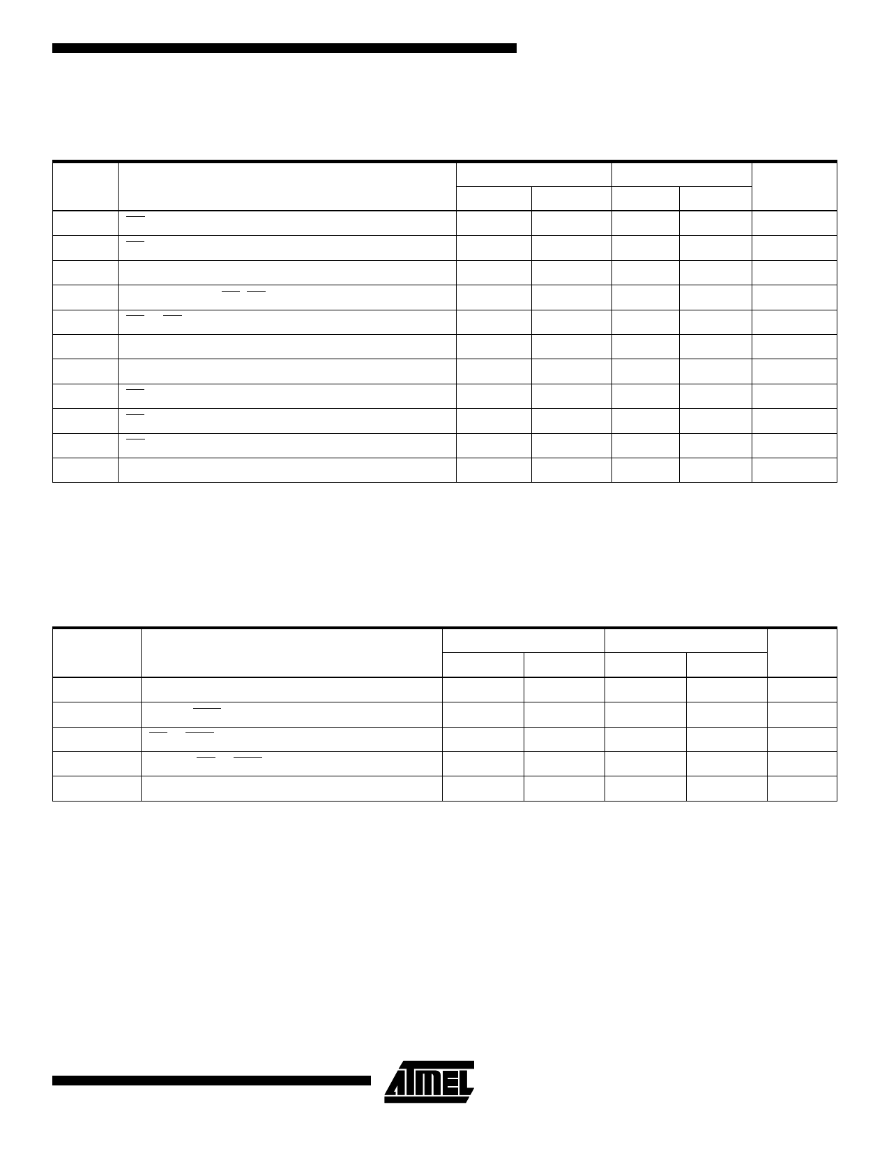
AC Characteristics for AT17C512/010
VCC = 5V ± 5% Commercial/VCC = 5V ± 10% Industrial/Military
Commercial
Industrial/Military(1)
Symbol Description
Min
Max
Min
Max
Units
TOE(2)
TCE(2)
TCAC(2)
OE to Data Delay
CE to Data Delay
CLK to Data Delay
30.0
35.0
ns
45.0
45.0
ns
50.0
50.0
ns
TOH
TDF()
Data Hold From CE, OE, or CLK
CE or OE to Data Float Delay
0.0
0.0
ns
50.0
50.0
ns
TLC
CLK Low Time
20.0
20.0
ns
THC
CLK High Time
20.0
20.0
ns
TSCE
CE Setup Time to CLK (to guarantee proper counting)
20.0
25.0
ns
THCE
CE Hold Time from CLK (to guarantee proper counting)
0.0
0.0
ns
THOE
OE High Time (guarantees counter Is reset)
20.0
20.0
ns
FMAX
Notes:
MAX Input Clock Frequency
15.0
15.0
1. Preliminary specifications for military operating range only.
2. AC test load = 50 pF.
3. Float delays are measured with 5 pF AC loads. Transition is measured ±200 mV from steady state active levels.
MHz
.
AC Characteristics for AT17C512/010 When Cascading
VCC = 5V± 5% Commercial/VCC = 5V ± 10% Industrial/Military
Commercial
Industrial/Military(1)
Symbol
Description
Min
Max
Min
Max
TCDF (3)
CLK to Data Float Delay
50.0
50.0
TOCK(2)
CLK to CEO Delay
35.0
40.0
TOCE(2)
CE to CEO Delay
35.0
35.0
TOOE(2)
RESET/OE to CEO Delay
30.0
30.0
FMAX
Notes:
MAX Input Clock Frequency
12.5
12.5
1. Preliminary specifications for military operating range only.
2. AC test load = 50 pF.
3. Float delays are measured with 5 pF AC loads. Transition is measured ±200 mV from steady state active levels.
Units
ns
ns
ns
ns
MHz
9
Share Link: 