AS1115-BQFT Ver la hoja de datos (PDF) - austriamicrosystems AG
NГәmero de pieza
componentes DescripciГіn
Fabricante
AS1115-BQFT Datasheet PDF : 24 Pages
| |||
AS1115
Datasheet - Detailed Description
acknowledge bit on the last byte that has been clocked out of the slave. In this case, the slave must leave the
data line HIGH to enable the master to generate the STOP condition.
- Figure 19 on page 9 details how data transfer is accomplished on the IВІC bus. Depending upon the state of the R/
W bit, two types of data transfer are possible:
- Master Transmitter to Slave Receiver. The first byte transmitted by the master is the slave address, followed by
a number of data bytes. The slave returns an acknowledge bit after the slave address and each received byte.
- Slave Transmitter to Master Receiver. The first byte, the slave address, is transmitted by the master. The slave
then returns an acknowledge bit. Next, a number of data bytes are transmitted by the slave to the master. The
master returns an acknowledge bit after all received bytes other than the last byte. At the end of the last received
byte, a not-acknowledge is returned. The master device generates all of the serial clock pulses and the START
and STOP conditions. A transfer is ended with a STOP condition or a repeated START condition. Since a
repeated START condition is also the beginning of the next serial transfer, the bus will not be released.
The AS1115 can operate in the following slave modes:
- Slave Receiver Mode. Serial data and clock are received through SDA and SCL. After each byte is received, an
acknowledge bit is transmitted. START and STOP conditions are recognized as the beginning and end of a serial
transfer. Address recognition is performed by hardware after reception of the slave address and direction bit.
- Slave Transmitter Mode. The first byte (the slave address) is received and handled as in the slave receiver
mode. However, in this mode the direction bit will indicate that the transfer direction is reversed. Serial data is
transmitted on SDA by the AS1115 while the serial clock is input on SCL. START and STOP conditions are recog-
nized as the beginning and end of a serial transfer.
IВІC Device Self Addressing
If this feature is used, 2 of the 16 key readback nodes can be left open or shorted for self-addressing. This is done with
KEYA together with SEGG and SEGF. This two nodes cannot be used for key-readback in this case. After startup all
devices have the predefined adress 0000000. A single command for self-addressing will update all connected AS1115.
This command has to be done after startup or everytime the AS1115 gets disconnected from the supply. The IВІC
address definition must be done with fixed connection, since IВІC detection is excluded from debounce time of key reg-
isters.
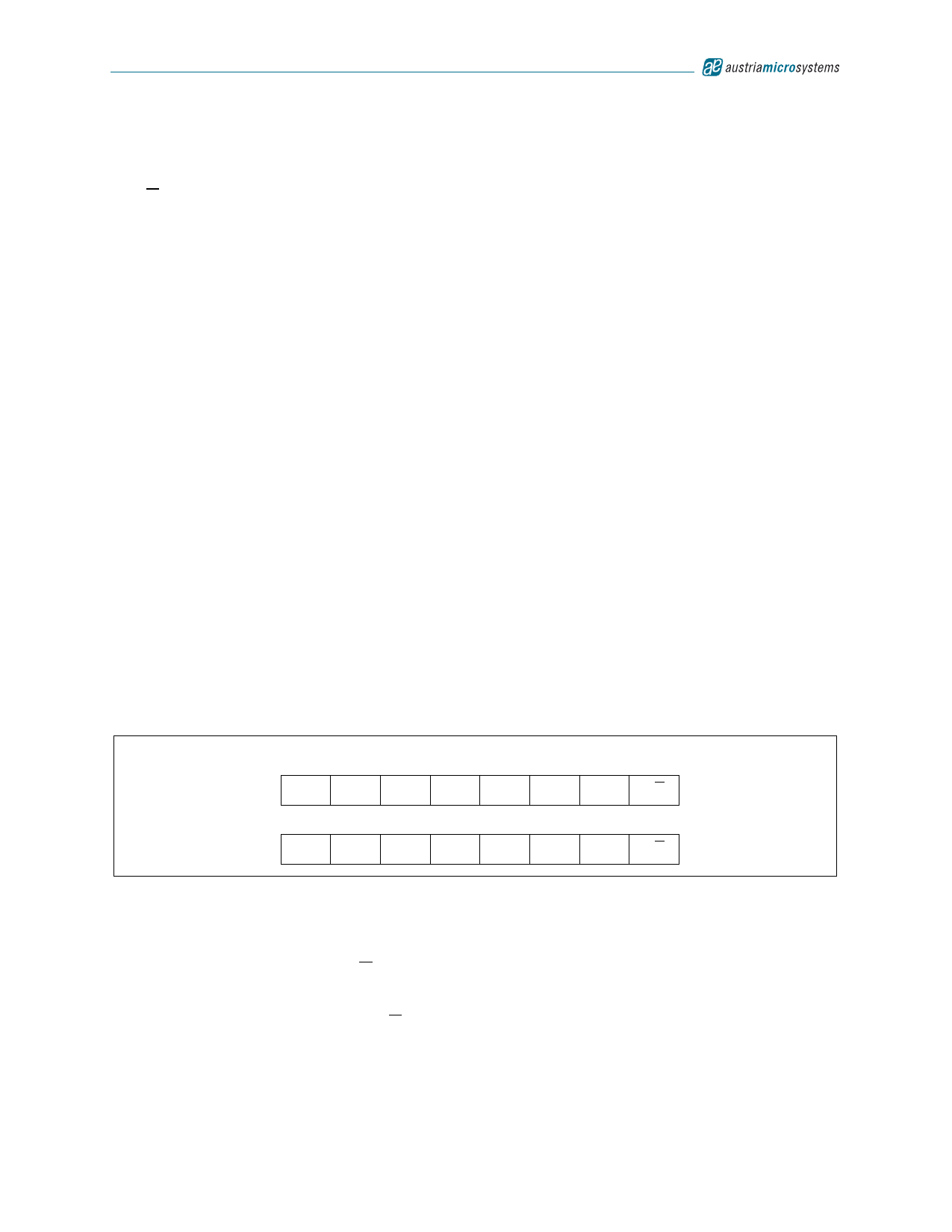
IВІC Device Address Byte
The address byte (see Figure 20) is the first byte received following the START condition from the master device.
Figure 20. IВІC Device Address Byte
MSB
6
5
4
3
2
1
LSB
predefined address:
0
0
0
0
0
0
0
R/W
MSB
6
5
4
3
2
1
LSB
updated address:
0
0
0
0
0
A1
A0
R/W
- The default slave address is factory-set to 0000000.
- The two LSB bits of the address byte are the device select bits, A0 to A1, which can be set by the self-adress
command after startup. A maximum of four devices with the same pre-set code can therefore be connected on
the same bus at one time.
- The last bit of the address byte (R/W) define the operation to be performed. When set to a 1 a read operation is
selected; when set to a 0 a write operation is selected.
Following the START condition, the AS1115 monitors the IВІC bus, checking the device type identifier being transmitted.
Upon receiving the address code, and the R/W bit, the slave device outputs an acknowledge signal on the SDA line.
www.austriamicrosystems.com
Revision 1.03
10 - 24
Share Link: 