APW7073A Ver la hoja de datos (PDF) - Anpec Electronics
Número de pieza
componentes Descripción
Fabricante
APW7073A Datasheet PDF : 20 Pages
| |||
APW7073A
Synchronous Buck PWM Controller
Features
• Single 12V Power Supply Required
• 0.6V Reference with 1% Accuracy
• Shutdown and Soft-Start Function
• Programmable Frequency Range from 50 kHz to
1000kHz
• Voltage Mode PWM Control Design
• Up to 100% Duty Cycle
• Over-Current Protection (OCP)
• SOP-14 Package
• Lead Free and Green Devices Available
(RoHS Compliant)
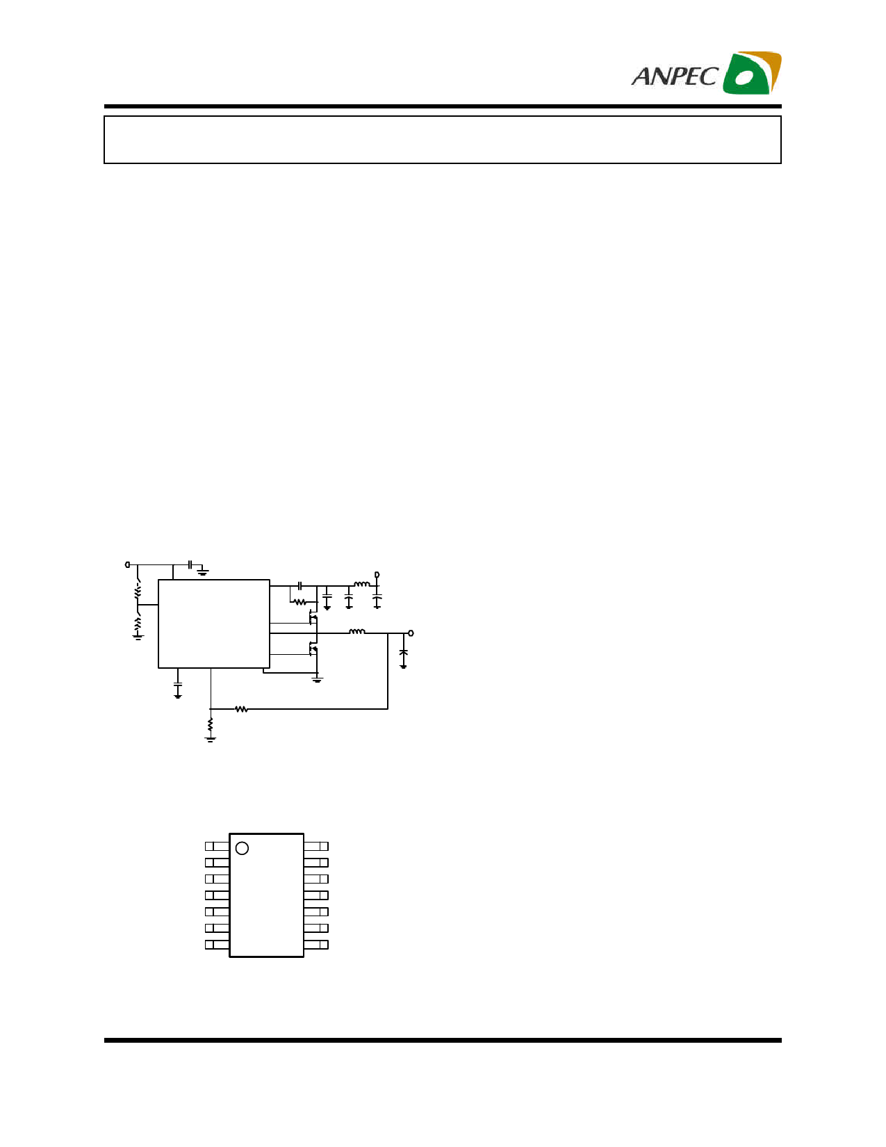
Typical Application Circuit
12V
ROCSET
V IN
RFS
APW7073A
L
V OUT
CSS
General Description
The APW7073A is a voltage mode and synchronous
PWM controller which drives dual N-channel MOSFETs.
The device integrates all of the controlling, monitoring,
and protecting functions into a single package, and pro-
vides one controlled power output with over-current
protection.
The APW7073A provides excellent regulation for output
load variation. The internal 0.6V temperature-compen-
sated reference voltage is designed to meet the require-
ment of low output voltage applications. The device in-
cludes a 200kHz free-running triangle-wave oscillator that
is adjustable from 50kHz to 1000kHz.
The APW7073A has been equipped with excellent pro-
tection functions: Power-On-Reset (POR) and Over-Cur-
rent Protection (OCP). The POR circuit can monitor the
VCC, EN, and OCSET voltages to make sure the supply
voltages exceed their threshold voltage while the con-
troller is running. The OCP monitors the output current
by using the voltage drop across the upper MOSFET’s RDS
. When the output current reaches the trip point, the IC
(ON)
shuts off the converter and initiates a new soft-start
process. After two over-current events are counted, the
device turns off both high-side and low-side MOSFETs
and the converter output is latched to be floating. It re-
quires a POR of VCC to restart.
Pin Configuration
RT 1
OCSET 2
SS 3
COMP 4
FB 5
EN 6
GND 7
SOP-14
14 VCC
13 PVCC
12 LGATE
11 PGND
10 BOOT
9 UGATE
8 PHASE
Applications
• DC-DC Power Supply
ANPEC reserves the right to make changes to improve reliability or manufacturability without notice, and
advise customers to obtain the latest version of relevant information to verify before placing orders.
Copyright © ANPEC Electronics Corp.
1
Rev. A.5 - Nov., 2012
www.anpec.com.tw
Share Link: 