APW7065C Ver la hoja de datos (PDF) - Anpec Electronics
Número de pieza
componentes Descripción
Fabricante
APW7065C Datasheet PDF : 19 Pages
| |||
APW7065C
Function Description
Power-On-Reset (POR)
The Power-On-Reset (POR) function of APW7065C con-
tinually monitors the input supply voltage (V ) and the
CC
COMP pin. The supply voltage (V ) must exceed its ris-
CC
ing POR threshold voltage. The POR function initiates
soft-start operation after VCC and COMP voltages exceed
their POR thresholds. For operation with a single +12V
power source, VIN and VCC are equivalent and the +12V
power source must exceed the rising VCC threshold. The
POR function inhibits operation at disabled status (V
COMP
is less than 1.2V). With both input supplies above their
POR thresholds, the device initiates a soft-start interval.
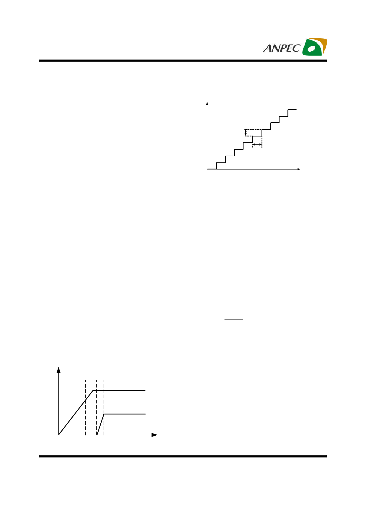
Soft-Start
Voltage(V)
FB
12.5mV
8/Fosc
Time
Figure 2. The Controlled Stepped FB Voltage
during Soft Start
The APW7065C has a built-in digital soft-start to control
the output voltage rise and limit the current surge during
the start-up. In Figure 1, when V exceeds rising POR
CC
threshold voltage, the delay time is counted from t1 to t2
and then soft-start will be enabled. During soft-start, an
internal ramp connected to the one of the positive inputs
of the Gm amplifier rises up from 0V to 2V to replace the
reference voltage (0.8V) until the ramp voltage reaches
the reference voltage. The soft-start interval is decided by
the oscillator frequency (300KHz). The formulation is given
by:
Tsoft−start = t3 − t2 = 512/FOSC = 1.7ms
Figure 2. shows more details of the FB voltage ramp. The
FB voltage soft-start ramp is formed with many small
steps of voltage. The voltage of one step is about 12.5mV in
FB, and the period of one step is about 8/F . This method
OSC
provides a controlled voltage rise and prevents the large
peak current to charge output capacitor.
Over-Current Protection
The over-current protection monitors the output current
by using the voltage drop across the lower MOSFET’s
RDS(ON) and this voltage drop will be compared with the
internal 0.29V reference voltage. If the voltage drop across
the lower MOSFET’s RDS(ON) is larger than 0.29V, an
over-current condition is detected. The IC shuts off the
converter and initiates a new soft-start process. After two
over-current events are counted, the device turns off both
high-side and low-side MOSFETs and the converter's
output is latched to be floating. It requires a POR of V to
CC
restart. The threshold of the over current limit is given by:
ILimit
=
0.29
RDS(ON)
For the over-current is never occurred in the normal oper-
ating load range; the variation of all parameters in the
above equation should be determined.
Voltage (V)
VCC
VOUT
- The MOSFET’s R is varied by temperature and
DS(ON)
gate to source voltage, the user should determine
the maximum RDS(ON) in manufacturer’s datasheet.
- The minimum Vocset should be used in the above
equation.
- Note that the ILIMIT is the current flow through the lower
MOSFET; I must be greater than maximum output
LIMIT
current and add the half of inductor ripple current.
t1 t2 t3
Figure 1. Soft Start Interval
Time
Copyright © ANPEC Electronics Corp.
10
Rev. A.2 - Mar., 2008
www.anpec.com.tw
Share Link: 