APL5910 Ver la hoja de datos (PDF) - Anpec Electronics
Número de pieza
componentes Descripción
Fabricante
APL5910 Datasheet PDF : 17 Pages
| |||
APL5910
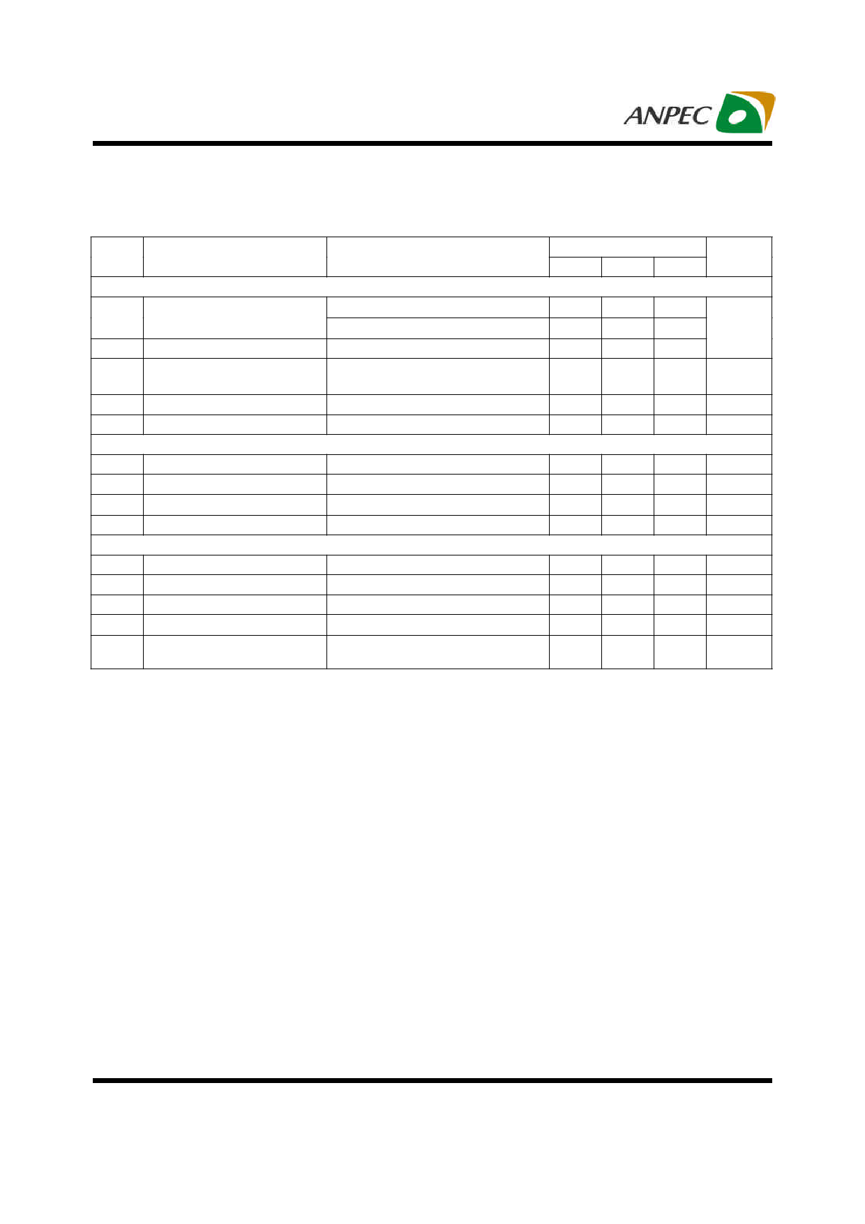
Electrical Characteristics (Cont.)
Refer to the typical application circuits. These specifications apply over VCNTL=5V, VIN=1.5V, VOUT=1.2V, and TA= -40 ~ 85oC, unless
otherwise specified. Typical values are at TJ=25oC.
Symbol
Parameter
Test Conditions
APL5910
Unit
Min. Typ. Max.
PROTECTIONS
ILIM Current-Limit Level
TJ=25οC
TJ= -40 ~ 125οC
ISHORT Short Current-Limit Level
VFB<0.2V
Short Current-Limit Blanking
Time
From beginning of soft-start
TSD Thermal Shutdown Temperature TJ rising
Thermal Shutdown Hysteresis
ENABLE AND SOFT-START
1.7
2.1
2.5
1.4
-
-
A
-
0.4
-
0.6
1.6
-
ms
-
170
-
oC
-
50
-
oC
EN Logic High Threshold Voltage VEN rising
EN Hysteresis
0.5
0.8
1.1
V
-
80
-
mV
EN Pull-High Current
TSS Soft-Start Interval
POWER-OK AND DELAY
EN=GND
-
5
-
µA
0.3
0.6
1
ms
VTHPOK
Rising POK Threshold Voltage
POK Threshold Hysteresis
VFB rising
90
92
94
%
-
8
-
%
POK Pull-Low Voltage
POK sinks 5mA
-
0.25
0.4
V
POK Debounce Interval
POK Delay Time
VFB<falling POK voltage threshold
-
10
-
µs
From VFB =VTHPOK to rising edge of the
VPOK
1
2
4
ms
Copyright © ANPEC Electronics Corp.
4
Rev. A.3 - Jun., 2009
www.anpec.com.tw
Share Link: 