APA4838 Ver la hoja de datos (PDF) - Anpec Electronics
Número de pieza
componentes Descripción
Fabricante
APA4838
Anpec Electronics

APA4838 Datasheet PDF : 29 Pages
| |||
APA4838
Application Descriptions (Cont.)
Output SE/BTL Operation
Output SE/BTL Operation (Cont.)
The ability of the APA4838 to easily switch between
BTL and SE modes is one of its most important costs
saving features. This feature eliminates the require-
ment for an additional headphone amplifier in appli-
cations where internal stereo speakers are driven in
BTL mode but external headphone or speakers must
be accommodated.
Internal to the APA4838, two separate amplifiers drive
–Out and +Out for each channel (see Figure 1). The
HP Sense input controls the operation of the follower
amplifier that drives +Left Out and +Right Out.
• When HP Sense is held low, the OP2 is turn on and
the APA4838 is in the BTL mode.
•When HP Sense is held high, the OP2 is in a high
output impedance state, which configures the
APA4838 as SE driver from -Out. I is reduced by
DD
approximately one-half in SE mode.
Control of the HP Sense input can be a logic-level
TTL source or a resistor divider network or the ste-
reo headphone jack with switch pin as shown in Ap-
plication Circuit.
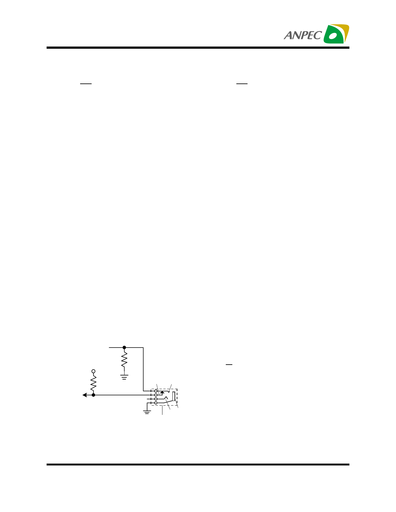
In Figure 2, input HP Sense operates as follows:
When the phonejack plug is inserted, the 1kΩ resis-
tor is disconnected and the HP Sense input is pulled
high and enables the SE mode.
When this input goes high level, the +Out amplifier is
shutdown causing the speaker to mute. The -Out
amplifier then drives through the output capacitor (CC)
into the headphone jack.
When there is no headphone plugged into the system,
the contact pin of the headphone jack is connected
from the signal pin, the voltage divider set up by re-
sistors 100kΩ and 1kΩ. Resistor 1kΩ then pulls low
the HP Sense pin, enabling the BTL function.
Docking Output Signal
APA4835 internal first amplifier is used as audio sig-
nal pre-amplfier and feedback resistor is connected
between Dock output pin and audio input pin.
However, the internal first amplifier’s closed-loop gain
can be adjusted using external resistors. Use Equa-
tion 2 to determine the input and feedback resistor
values for a desired gain.
VDD
100kΩ
HP sense
1kΩ
Control
Pin
Ring
Sleeve
Tip
Headphone Jack
Figure 2: HP Sense input selection by phonejack
plug
AV
=
-
RF
Ri
(2)
The Dock output signal provides low distortion audio
quality for light driving output. ex. active speaker,
monitors or audio/visual equipment. These two out-
puts can driving load of >1kΩ with rail-to-rail output
and output coupling capacitor is required when using
these outputs.
Copyright ANPEC Electronics Corp.
18
Rev. A.1 - Apr., 2003
www.anpec.com.tw
Share Link: