AN8018SA Ver la hoja de datos (PDF) - Panasonic Corporation
Número de pieza
componentes Descripción
Fabricante
AN8018SA
Panasonic Corporation

AN8018SA Datasheet PDF : 26 Pages
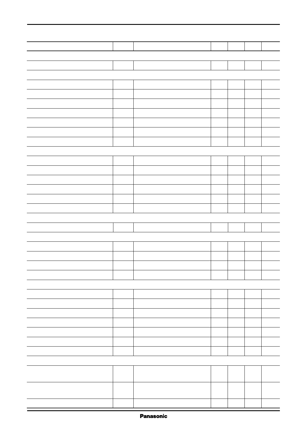
| |||
AN8018SA
Voltage Regulators
s Electrical Characteristics at VCC = 2.4 V, CREF = 0.1 µF, Ta = 25°C (continued)
Parameter
Symbol
Conditions
Min Typ Max Unit
U.V.L.O. block
Circuit operation start voltage
Error amplifier 1 block
VUON
1.59 1.67 1.75 V
Input offset voltage
Common-mode input voltage range
Input bias current 1
High-level output voltage 1
Low-level output voltage 1
Output source current 1
Output sink current 1
Error amplifier 2 block
VIO
VICR
IB1
VEH1
VEL1
ISO(FB)1
ISI(FB)1
−6 +6 mV
0.3 0.7 V
− 0.6 − 0.2 µA
0.83 0.93 1.03 V
0.2 V
−61 −47 −33 µA
33 47 61 µA
Input threshold voltage
Input bias current 2
High-level output voltage 2
Low-level output voltage 2
Output source current 2
Output sink current 2
Oscillator block
VTH
IB2
VEH2
VEL2
ISO(FB)2
ISI(FB)2
1.16 1.19 1.22 V
0.2 0.8 µA
0.83 0.93 1.03 V
0.2 V
−61 −47 −33 µA
33 47 61 µA
Output off threshold voltage
Output 1 block
VTH(OSC)
0.8 0.9 1.0 V
Oscillation frequency 1
Output duty ratio 1
Output saturation voltage
Output leak current
Output 2 block
fOUT1 RT = 12 kΩ, CT = 330 pF
Du1
VO(SAT) IO = 30 mA
IOLE VCC = 14 V
185 205 225 kHz
75 80 85 %
0.5 V
1 µA
Oscillation frequency 2
Output duty ratio 2
High-level output voltage
Low-level output voltage
Output source current
Output sink current
Pull-down resistance
PWM1 block
fOUT2 RT = 12 kΩ, CT = 330 pF
Du2
VOH IO = −10 mA, RB = 820 Ω
VOL IO = 10 mA, RB = 820 Ω
ISO(OUT) VO = 0.7 V, RB = 820 Ω
ISI(OUT) VO = 0.7 V, RB = 820 Ω
RO
185 205 225 kHz
72 77 82 %
1.4 V
0.2 V
−40 −30 −20 mA
20 mA
20 30 40 kΩ
Output full-off input threshold
voltage 1
VT0-1 Duty = 0%
0.28 0.30 V
Output full-on input threshold
voltage 1
VT100-1 Duty = 100%
0.65 0.72 V
Input current 1
IDT1 VDT1 = 0.4 V
−1.1 − 0.5 µA
4
Share Link: