AN6291S Ver la hoja de datos (PDF) - Panasonic Corporation
Número de pieza
componentes Descripción
Fabricante
AN6291S
Panasonic Corporation

AN6291S Datasheet PDF : 7 Pages
| |||
ICs for Cassette, Cassette Deck
AN6291, AN6291S
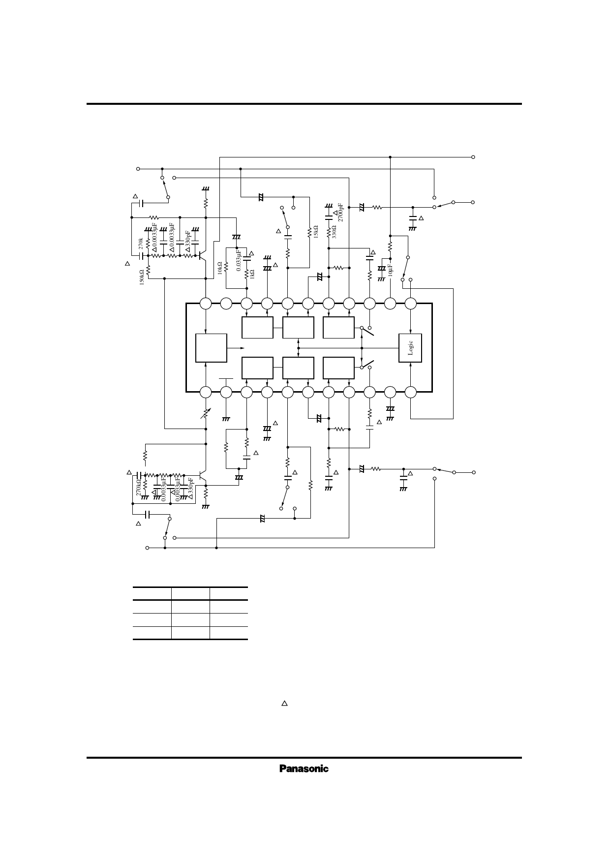
s Application Circuits
1 Switching circuit of recording/playback
Input
–B
E
D
0.1µF
33kΩ
SW1a
3.3kΩ
0.1µF 4.7kΩ 33kΩ 6.8kΩ
2SC1327
22
0.1µF
–+
D
E
10µF 560Ω
+–
SW1b
+ 0.47µF
6800pF
–
15kΩ
1kΩ
6800pF
–
+ 10µF
51kΩ
+
22µF
–+
15kΩ –
D
OFF
ON
SW2a
0.01µF
SW1e
E
*2
21 20 19 18 17 16 15 14 13 12
+VCC
Output
–B
Current
Source
SUB
RMS– B
RMS – A
CCA– B
OP
Amp.– B
CCA– A
OP
Amp.– A
1
2
3
4
5
6
7
8
9 10 11
*1
+
2k
–+
15kΩ
1µF
–
(B)
+
– 10µF
22µF 51kΩ
6800pF
150kΩ
2SC1327
1µF 4.7kΩ 33kΩ 6.8kΩ
10kΩ
3.3kΩ
1kΩ
0.033µF
–
0.47µF
+
6800pF
15kΩ
SW1e
330Ω + – 560Ω
2700
pF
51kΩ
10µF
0.01µF
ON
OFF
SW2b
33kΩ
0.1µF
D
SW1d
E
Input
–A
D
E
–+
0.1µF
Output
–A
Logical condition of recording/playback
Pin11
VCC
Open
VCC
Pin12
Open
VCC
VCC
Mode
DECODE
ENCODE
OFF
* 1 Signals of 1kHz, 20mV are applied to the input of both channels at the same time, sinking current into the Pin13 should be
adjusted to 15µA±5%. Standard value at VCC=3V is about 1kΩ.
* 2 External circuit should not be connected with Pin21. Connected in the IC.
* 3 Users should follow the latest technical information from dbx company. Constant number might be changed.
Note 1) All the resistors and the capacitor with the mark should be used in the error less than ±5%.
Note 2) S1a~ S1e : Switch record, playback (Above figure shows “PLAYBACK” mode).
Note 3) S2a~ S2b : dbx ON-OFF switch (Above figure shows “ON” mode).
Share Link: