DS1820 Ver la hoja de datos (PDF) - Dallas Semiconductor -> Maxim Integrated
Número de pieza
componentes Descripción
Fabricante
DS1820 Datasheet PDF : 27 Pages
| |||
DS1820
1–WIRE CRC CODE Figure 7
INPUT
(MSB)
XOR
XOR
(LSB)
XOR
MEMORY
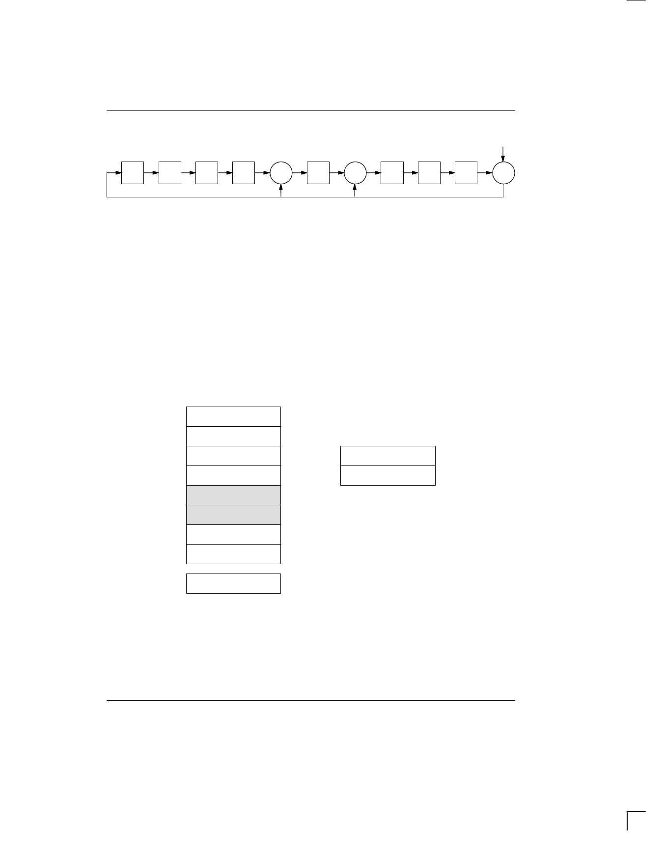
The DS1820’s memory is organized as shown in
Figure 8. The memory consists of a scratchpad RAM
and a nonvolatile, electrically erasable (E2) RAM, which
stores the high and low temperature triggers TH and TL.
The scratchpad helps insure data integrity when com-
municating over the 1–Wire bus. Data is first written to
the scratchpad where it can be read back. After the data
has been verified, a copy scratchpad command will
transfer the data to the nonvolatile (E2) RAM. This pro-
cess insures data integrity when modifying the memory.
The scratchpad is organized as eight bytes of memory.
The first two bytes contain the measured temperature
information. The third and fourth bytes are volatile
copies of TH and TL and are refreshed with every pow-
er–on reset. The next two bytes are not used; upon
reading back, however, they will appear as all logic 1’s.
The seventh and eighth bytes are count registers, which
may be used in obtaining higher temperature resolution
(see “Operation–measuring Temperature” section).
There is a ninth byte which may be read with a Read
Scratchpad command. This byte contains a cyclic
redundancy check (CRC) byte which is the CRC over all
of the eight previous bytes. This CRC is implemented in
the fashion described in the section titled “CRC Genera-
tion”.
DS1820 MEMORY MAP Figure 8
SCRATCHPAD
TEMPERATURE LSB
TEMPERATURE MSB
TH/USER BYTE 1
TL/USER BYTE 2
RESERVED
RESERVED
COUNT REMAIN
COUNT PER °C
BYTE
0
1
2
3
4
5
6
7
E2 RAM
TH/USER BYTE 1
TL/USER BYTE 2
CRC
8
030598 8/27
Share Link: 