DS2890/TR Ver la hoja de datos (PDF) - Dallas Semiconductor -> Maxim Integrated
NĂşmero de pieza
componentes DescripciĂłn
Fabricante
DS2890/TR Datasheet PDF : 27 Pages
| |||
DS2890
POWER
With the charge pump off, the DS2890 can derive its power entirely from the 1-Wire bus by storing
energy on an internal capacitor during periods of time when the 1-Wire bus is in a high state. During bus
low times the device continues to operate from the energy stored on the internal capacitor; the capacitor is
then recharged when the bus returns to a high state. This technique of operating entirely from the 1-Wire
bus by powering from energy stored on an internal capacitor during bus low times in known as âparasite
poweredâ operation. As an option, an auxiliary power source may be connected to the VDD power pin.
The auxiliary power mode is appropriate for applications where device charge pump activation is
necessary, the device may be temporarily disconnected from the 1-Wire bus, or bus low times may be
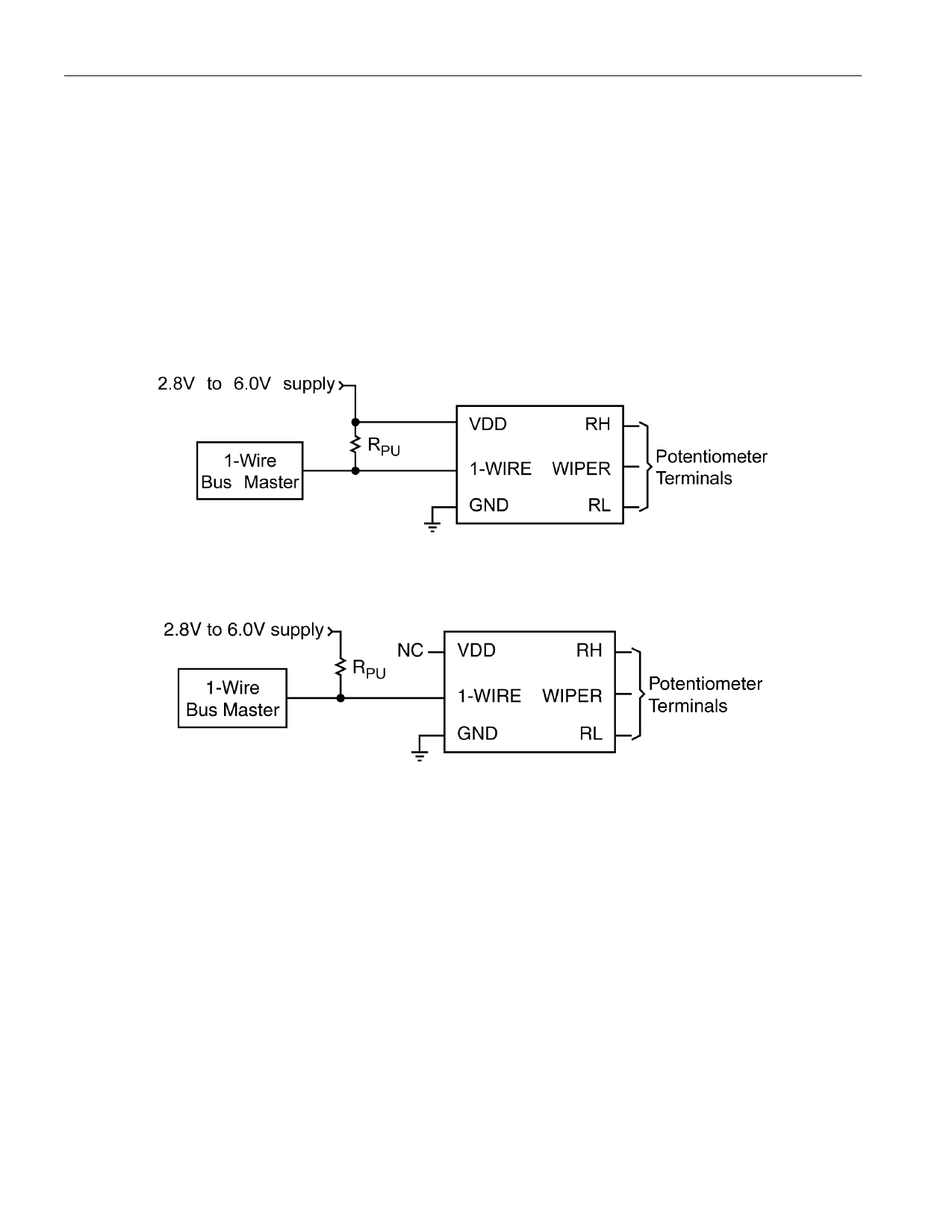
very long. See Figure 5 for example configurations for both power modes.
Figure 5. POWER SUPPLY CONFIGURATION OPTIONS
(a) Auxiliary VDD Supply Configuration
(b) 1-Wire Parasite Power Configuration
POTENTIOMETER WIPER RESISTANCE AND CHARGE PUMP
CONSIDERATIONS
A simplified diagram of the DS2890 resistor array is shown in Figure 6. In this figure the rDS resistance
of the wiper transistors in Figure 1 are modeled as wiper resistance RWIPER. The value of RWIPER varies
with device configuration, operational state, and wiper terminal voltage. If an auxiliary external VDD
supply configuration is used as shown In Figure 5a, the DS2890 charge pump may be enabled to reduce
potentiometer wiper resistance. A consequence of enabling the charge pump is increased device power
consumption. This increase is beyond the level that can be supported when operating in 1-Wire parasite
power mode (see POWER section). Therefore if it is necessary to enable the charge pump in an
application, the power supply configuration as shown in Figure 5a must be used. Figure 7 and Figure 8
are graphs of wiper resistance with the charge pump turned ON and OFF respectively.
7 of 27
Share Link: 