DS2890V-000 Ver la hoja de datos (PDF) - Dallas Semiconductor -> Maxim Integrated
NГәmero de pieza
componentes DescripciГіn
Fabricante
DS2890V-000 Datasheet PDF : 27 Pages
| |||
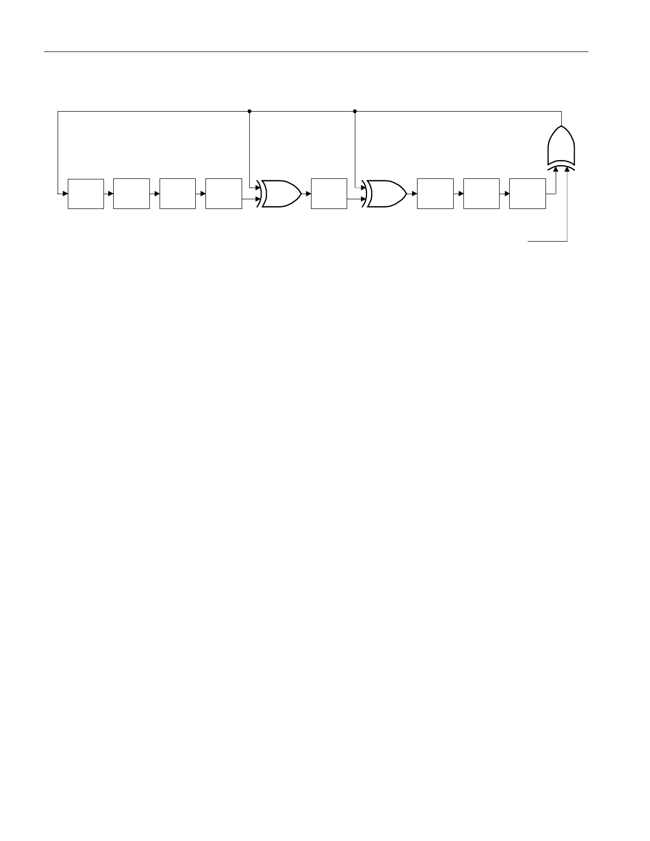
Figure 11. 1-WIRE CRC GENERATOR
Polynomial = X8 + X5 + X4 + 1
DS2890
R
S
1ST
2ND
3RD
4TH
STAGE STAGE STAGE STAGE
X0
X1
X2
X3
5TH
STAGE
X4
6TH
7TH
8TH
STAGE STAGE STAGE
X5
X6
X7
X8
INPUT DATA
POTENTIOMETER FUNCTION COMMANDS
Once the bus master has completed a ROM command sequence, one of six DS2890 potentiometer
function commands can be issued. The Potentiometer Function Command flow charts, Figure 16 and
Figure 17, describe the protocols necessary for adjusting or reading the potentiometer wiper position or
controlling the operating state of the DS2890. All potentiometer functions consist of a single command
byte followed by one or more bytes of data or control written/read by the bus master. All data transferred
between the DS2890 and the bus master are communicated least significant bit first.
READ POSITION [F0H]
The Read Position command is used to obtain the wiper setting of the potentiometer currently addressed
by the Control Register. Although the DS2890 is a single element potentiometer, wiper addressing still
applies and the Control Register wiper number used for addressing must be set accordingly. In addition
to wiper position, the Control Register byte will be returned with a Read Position command. This enables
the bus master to easily confirm/determine the currently addressed potentiometer wiper. Following the
Read Position command byte, the bus master reads 16 bits to obtain first the Control Register byte then
the wiper position byte. The DS2890 will respond with 0вҖҷs to additional reads after the 8 bit of the
position byte. The Read Position command is terminated with a Reset pulse.
WRITE POSITION [0FH]
The Write Position command is used to set the position of the currently addressed potentiometer wiper.
Although the DS2890 is a single element potentiometer, wiper addressing still applies and the Control
Register wiper number used for addressing must be set accordingly. The bus master follows the Write
Position command byte with an 8-bit wiper position value. Following the 8th bit of the position byte, the
bus master reads back the 8-bit position value from the DS2890 to confirm that the value was received
correctly by the device. If an incorrect value is read back, the bus master must issue a Reset pulse and
repeat the sequence. If the value read back is correct, the bus master then sends the 8-bit release code
(96h). If the DS2890 accurately receives the release code, the wiper position is updated and the device
will respond with 0вҖҷs to additional reads by the bus master. If an invalid release code is received, no
change is made to the wiper position and the device will respond with 1вҖҷs to additional reads by the bus
master. The Write Position command is terminated with a Reset pulse.
11 of 27
Share Link: 