AG8889N Ver la hoja de datos (PDF) - ELAN Microelectronics
Número de pieza
componentes Descripción
Fabricante
AG8889N Datasheet PDF : 7 Pages
| |||
AG8889
CALL WAITING DECODER
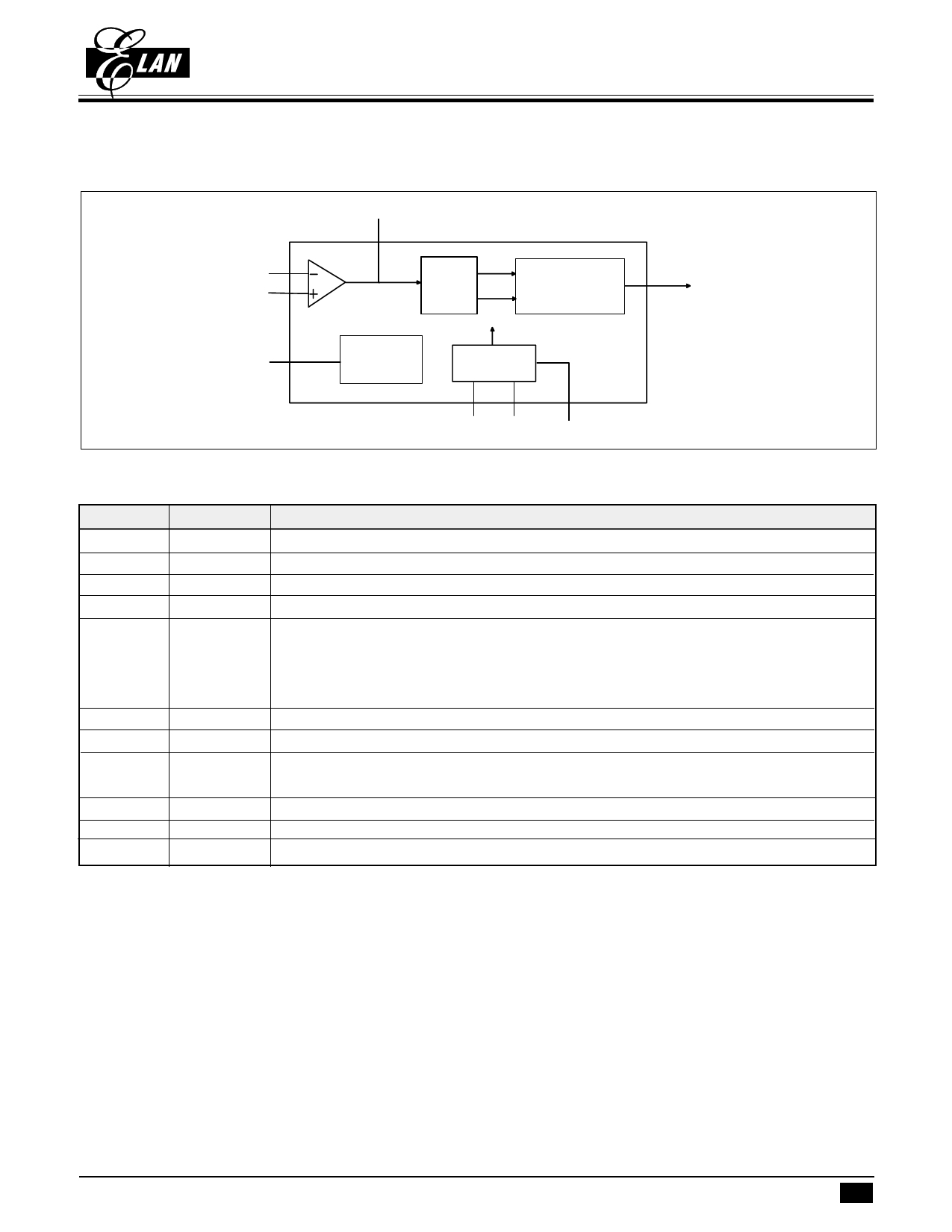
V. FUNCTIONAL BLOCK DIAGRAM
OPO
TIP
RING
Tone
DO
Filter
Detection Block
VREF
Vdd/2 Voltage
Reference
Clock
Generator
OSCI OSCO PWD
VI. PIN DESCRIPTIONS
Pin
I/O
Description
TIP
I
Tip in should be connected with twisted pair
RING
I
Ring in should be connected with twisted pair
OPO
O
Output of OP Amp
VREF
Reference voltage Vref = 1/2 Vdd
PWD
I
This pin is normal low enabling chip on normal operation and ready to detect CAS
tone signals.
This active high input sets the chip into power down mode and disable oscillator to
save power.
OSCI
I
3.58MHz oscillator in
OSCO
O
3.58MHz oscillator out
DO
O
DO : used as output, this pin determines whether DO signal is valid or not. High is
valid. Normal low.
VDD
Power
GND
Ground
NC
Non connected
VII. FUNCTIONAL DESCRIPTIONS
Call Waiting service works by alerting a customer engaged in a telephone call to a new incoming call. This way the
customer can still receive important calls while engaged in a current call. The CALL WAITING DECODER can detect
CAS(Call-Waiting Alerting Signal 2130Hz plus 2750Hz) and generate a valid signal on the data pin.
The call waiting decoder is designed to support the Caller Number Deliver feature, which is offered by regional Bell
Operating Companies. The call waiting decoder has three blocks, including differential amplifier, tone filter detection block
In a typical application, this IC receives Tip and Ring signals from twisted pairs. The signals as inputs of differential
amplifier, and the differential amplifier sends input signal to a band pass tone filter. Once the signal is filtered, the
digital detection block decodes the information. The output data made available at DO pin.
This IC is used for detecting CAS signals. Once the signal is detected, the detection indication is shown on the data
output DO pin. The DO pin is normal low. When this IC detects 2130Hz and 2750Hz frequency at the same time, then
DO pin goes to high.
* This specification are subject to be changed without notice.
8.8.2000 2
Share Link: 