ADP3031 Ver la hoja de datos (PDF) - Analog Devices
Número de pieza
componentes Descripción
Fabricante
ADP3031 Datasheet PDF : 8 Pages
| |||
PRELIMINARY TECHNICAL DATA
ADP3031
“grounded” it runs at its highest frequency. A resistor from
RT to ground can be used to set intermediate operating
frequencies.
Because of the large currents which flow in the main
MOSFET switch, it is provided with a separate PGND
return to the negative supply terminal, to avoid corrupting
the small signal return, GND, that can be used as a sense
line at the output load point.
APPLICATION INFORMATION
Frequency Selection
The ADP3031's frequency can be user selected to operate at either
600 KHz or 2 MHz and programmable by setting the RT pin. Tie
RT to GND for 2 MHz operation. For 600 KHz operation, float the
RT pin.
The nominal resistance at the RT pin to get a switching
frequency, fSW, is given by:
RT
(Ω)
=
320,000
x
(2,000,000
-
f )/(3.6667
SW
x
f
SW
–
2,000,000)
(1)
Output Voltage
The ADP3031 features an adjustable output voltage range of
V to 12 V. The output voltage is fed back to the ADP3031
IN
via resistor dividers R1 and R2 (Figure 1.). The feedback
voltage is 1.233 V, so the output voltage is set by the formula:
V
OUT
=
1.233
×
(
1+
R1/R2)
(2)
Since the feedback bias current is 100 nA maximum, R2 may
have a value up to 100 KΩ with minimum error due to the bias
current.
Inductor Selection
For most of the applications, the inductor used with the
ADP3031 should be in the range of 2 µH to 22 µH. Several
inductor manufacturers are listed in Table 1. When select-
ing an inductor, it is important to make sure that the
inductor used with the ADP3031 is able to handle the peak
current without saturation and that the peak current is
below the current limit of the ADP3031.
As a rule, powdered iron cores saturate softly, whereas
Ferrite cores saturate abruptly. Open drum core inductors
tend to saturate gradually, are low cost and are small in size,
making these types of inductors attractive in many applica-
tions. However, care must be exercised in their placement
because they have high magnetic fields. In applications that
are sensitive to magnetic fields, shielded geometries are
recommended.
In addition, inductor losses must be considered. Both core
and copper losses contribute to loss in converter efficiency.
To minimize core losses, look for inductors rated for
operation at high switching frequencies. To minimize
copper losses, it is best to use low dc resistance inductors.
Typically, it is best to use an inductor with a dc resistance
lower than 20 mΩ per µH.
The inductor value can be estimated using the following:
L = (VOUT - VIN) × MSLOPE
Where MSLOPE = scaling factor for proper slope compen-
sation.
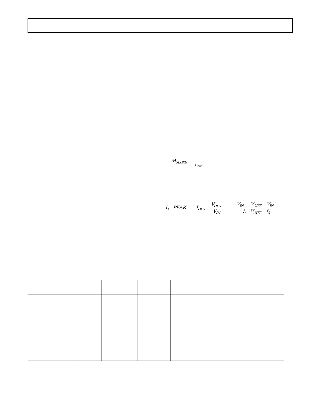
MSLOPE
= 1.456
fSW
Choose the closest standard inductor value as a starting
point.
The corresponding peak inductor current can then be
calculated:
IL
(PEAK )
=
IOUT
× VOUT
VIN
+
1
2
VIN × (VOUT
L × VOUT
− VIN
× fS
)
(3)
It is recommended to try several different inductor values,
sizes and types to find the best inductor for the application.
In general, large inductor values lead to lower ripple
current, less output noise, and either larger size or higher
DC resistance. Conversely, low inductor values lead to
higher ripple current, more noise, and either smaller size or
lower DC resistance. The final inductor selection should be
based on the best trade-off of size, cost, and performance.
Part
CMD4D11-2R2MC
CMD4D11-4R7MC
CDRH4D28-100
CDRH5D18-220
CR43-4R7
CR43-100
DS1608-472
DS1608-103
D52LC-4R7M
D52LC-100M
L(µH)
2.2
4.7
10
22
4.7
10
4.7
10
4.7
10
Table 1. Inductor Manufacturers
Max DC
Current
Max DCR Height
mΩ
(mm)
0.95
116
1.2
0.75
216
1.2
1.00
128
3.0
0.80
290
2.0
1.15
109
3.5
1.04
182
3.5
1.40
60
2.9
1.00
75
2.9
1.14
87
2.0
0.76
150
2.0
Vendor
Sumida
847-956-0666
www.sumida.com
Coilcraft
847-639-6400 www.coilcraft.com
Toko
847-297-0070 www.tokoam.com
REV. PrB
–5–
Share Link: 