ADM8694AN Ver la hoja de datos (PDF) - Analog Devices
Número de pieza
componentes Descripción
Fabricante
ADM8694AN Datasheet PDF : 16 Pages
| |||
ADM8690–ADM8695
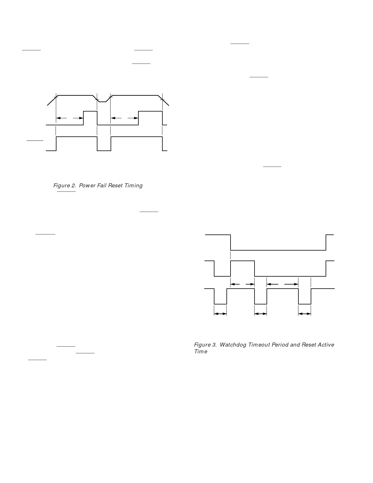
Power Fail RESET Output
RESET is an active low output that provides a RESET signal
to the Microprocessor whenever VCC is at an invalid level.
When VCC falls below the reset threshold, the RESET output
is forced low. The nominal reset voltage threshold is 4.65 V
(ADM8690/ADM8691/ADM8694/ADM8695) or 4.4 V
(ADM8692/ADM8693).
VCC
V2
V1
V2
V1
RESET
t1
t1
LOW LINE
t1 = RESET TIME
V1 = RESET VOLTAGE THRESHOLD LOW
V2 = RESET VOLTAGE THRESHOLD HIGH
HYSTERESIS = V2–V1
Figure 2. Power Fail Reset Timing
On power-up, RESET will remain low for 50 ms (200 ms for
ADM8694 and ADM8695) after VCC rises above the appropri-
ate reset threshold. This allows time for the power supply and
microprocessor to stabilize. On power-down, the RESET out-
put remains low with VCC as low as 1 V. This ensures that the
microprocessor is held in a stable shutdown condition.
This RESET active time is adjustable on the ADM8691/
ADM8693/ADM8695 by using an external oscillator or by
connecting an external capacitor to the OSC IN pin. Refer to
Table I and Figure 4.
The guaranteed minimum and maximum thresholds of the
ADM8690/ADM8691/ADM8694/ADM8695 are 4.5 V and
4.73 V, while the guaranteed thresholds of the ADM8692/
ADM8693 are 4.25 V and 4.48 V. The ADM8690/ADM8691/
ADM8694/ADM8695 is, therefore, compatible with 5 V sup-
plies with a +10%, –5% tolerance while the ADM8692/
ADM8693 is compatible with 5 V ± 10% supplies. The reset
threshold comparator has approximately 50 mV of hysteresis.
The response time of the reset voltage comparator is less than 1
µs. If glitches are present on the VCC line which could cause
spurious reset pulses, then VCC should be decoupled close to
the device.
In addition to RESET the ADM8691/ADM8693/ADM8695
contain an active high RESET output. This is the complement
of RESET and is intended for processors requiring an active
high RESET signal.
Watchdog Timer RESET
The watchdog timer circuit monitors the activity of the micro-
processor in order to check that it is not stalled in an indefinite
loop. An output line on the processor is used to toggle the
Watchdog Input (WDI) line. If this line is not toggled within the
selected timeout period, a RESET pulse is generated. The
nominal watchdog timeout period is preset at 1.6 seconds on the
ADM8690/ADM8692/ADM8694. The ADM8691/ADM8693/
ADM8695 may be configured for either a fixed “short” 100 ms
or a “long” 1.6 second timeout period or for an adjustable
timeout period. If the “short” period is selected, some systems
may be unable to service the watchdog timer immediately after a
reset, so the ADM8691/ADM8693/ADM8695 automatically se-
lects the “long” timeout period directly after a reset is issued.
The watchdog timer is restarted at the end of reset, whether the
reset was caused by lack of activity on WDI or by VCC falling be-
low the reset threshold.
The normal (short) timeout period becomes effective following
the first transition of WDI after RESET has gone inactive. The
watchdog timeout period restarts with each transition on the
WDI pin. To ensure that the watchdog timer does not time out,
either a high-to-low or low-to-high transition on the WDI pin
must occur at or less than the minimum timeout period. If WDI
remains permanently either high or low, reset pulses will be
issued after each “long” (1.6 s) timeout period. The watchdog
monitor can be deactivated by floating the Watchdog Input
(WDI) or by connecting it to midsupply.
WDI
WDO
RESET
t2
t3
t1
t1
t1
t1 = RESET TIME
t2 = NORMAL (SHORT) WATCHDOG TIMEOUT PERIOD
t3 = WATCHDOG TIMEOUT PERIOD IMMEDIATELY FOLLOWING A RESET
Figure 3. Watchdog Timeout Period and Reset Active
Time
–6–
REV. 0
Share Link: 