ADL5360 Ver la hoja de datos (PDF) - Analog Devices
Número de pieza
componentes Descripción
Fabricante
ADL5360 Datasheet PDF : 9 Pages
| |||
Preliminary Technical Data
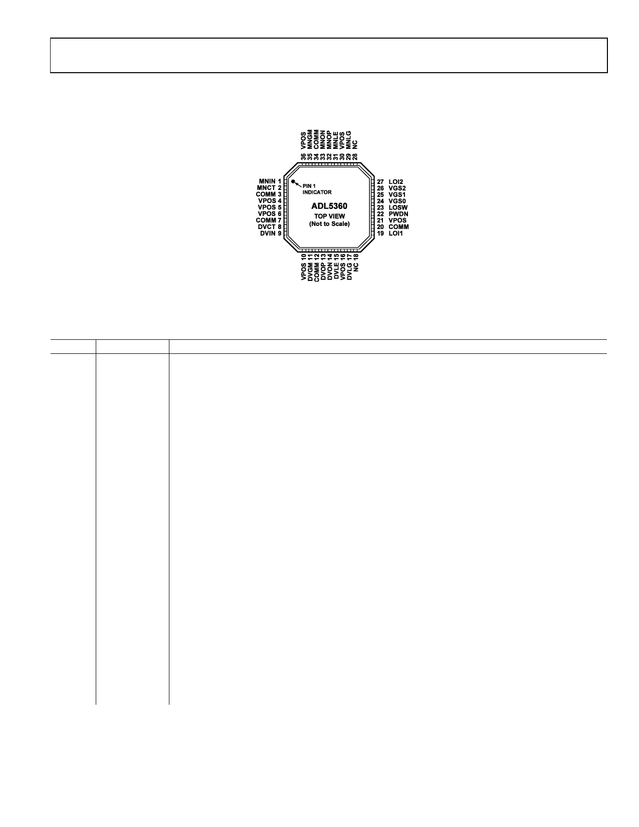
PIN CONFIGURATION AND FUNCTION DESCRIPTIONS
ADL5360
Figure 2. Pin Configuration
Table 3. Pin Function Descriptions
Pin No. Mnemonic
Function
1
MNIN
RF Input for Main Channel. Internally matched to 50Ω. Must be ac-coupled.
2
MNCT
Center Tap for Main Channel Input Balun. Should be bypassed to ground using low inductance capacitor.
3, 5, 7,
12, 20,
34
COMM
Device Common (DC Ground).
4,, 6, 10,
16, 21,
30, 36
VPOS
Positive Supply Voltage.
8
DVCT
Center Tap for Diversity Channel Input Balun. Should be bypassed to ground using low inductance capacitor.
9
DVIN
RF Input for Diversity Channel. Internally matched to 50Ω. Must be ac-coupled.
11
DVGM
Diverstiy Amplifier Bias Setting. Connect 1.2kΩ resistor to ground for typical operation.
13, 14
DVOP, DVON
Diversity Channel Differential Open-Collector Outputs. DVOP and DVON should be pulled-up to VCC using
pull-up choke inductors.
15
DVLE
Diversity Channel External Inductor. Connect 10nH inductor to ground for typical operation.
17
DVLG
Diverstiy Channel LO Buffer Bias Setting. Connect 390Ω resistor to ground for typical operation.
18, 28 NC
No Connect.
19,
L0I1
Local Oscillator Input 1. Internally matched to 50Ω. Must be ac-coupled.
22
PWDN
Connect to Ground for Normal Operation. Connect pin to 3.3V for disable mode.
23
LOSW
Local Oscillator Input Selection Switch. Set LOSW high to select LOI1, and set low to select LOI2.
24, 25,
26
VGS0, VGS1,
VGS2
Gate to Source Control Voltages. For typical operation set VGS2 high and VGS0 and VGS1 to low logic level.
27
LOI2
Local Oscillator Input 2. Internally matched to 50Ω. Must be ac-coupled.
29
MNLG
Main Channel LO Buffer Bias Setting. Connect 390Ω resistor to ground for typical operation.
31
MNLE
Main Channel External Inductor. Connect 10nH inductor to ground for typical operation.
32, 33
MNOP, MNON Main Channel Differential Open-Collector Outputs. MNOP and MNON should be pulled-up to VCC using pull-
up choke inductors.
35
MNGM
Main Amplifier Bias Setting. Connect 1.2kΩ resistor to ground for typical operation.
REV. PrA | Page 5 of 9
Share Link: 