ADE7751 Ver la hoja de datos (PDF) - Analog Devices
Número de pieza
componentes Descripción
Fabricante
ADE7751 Datasheet PDF : 16 Pages
| |||
ADE7751
PRELIMINARY TECHNICAL DATA
THEORY OF OPERATION
The two ADCs digitize the voltage and current signals from the
current and voltage transducers. These ADCs are 16-bit second
order sigma-delta converters with an oversampling rate of 900 kHz.
This analog input structure greatly simplifies transducer interfacing
by providing a wide dynamic range for direct connection to the
transducer and also by simplifying the antialiasing filter design.
A programmable gain stage in the current channel further
facilitates easy transducer interfacing. A high-pass filter in the
current channel removes any dc component from the current
signal. This eliminates any inaccuracies in the real power calcu-
lation due to offsets in the voltage or current signals—see
HPF and Offset Effects section.
The real power calculation is derived from the instantaneous
power signal. The instantaneous power signal is generated by a
direct multiplication of the current and voltage signals. In order
to extract the real power component (i.e., the dc component), the
instantaneous power signal is low-pass filtered. Figure 2 illustrates
the instantaneous real power signal and shows how the real power
information can be extracted by low-pass filtering the instantaneous
power signal. This scheme correctly calculates real power for
nonsinusoidal current and voltage waveforms at all power factors.
All signal processing is carried out in the digital domain for
superior stability over temperature and time.
are sinusoidal, the real power component of the instantaneous
power signal (i.e., the dc term) is given by:
V
×
2
I
×
cos
(60°)
(1)
This is the correct real power calculation.
INSTANTANEOUS
POWER SIGNAL
INSTANTANEOUS
REAL POWER SIGNAL
V؋I
2
0V
CURRENT
VOLTAGE
INSTANTANEOUS INSTANTANEOUS
POWER SIGNAL REAL POWER SIGNAL
V؋I ؋ cos(60؇)
2
0V
CH1
CH2
PGA
ADC
HPF
MULTIPLIER
ADC
DIGITAL-TO-
FREQUENCY
⌺
LPF
F1
F2
DIGITAL-TO-
FREQUENCY
⌺
CF
INSTANTANEOUS
POWER SIGNAL – p(t)
INSTANTANEOUS REAL
POWER SIGNAL
V؋I
p(t) = i(t)؋v(t)
WHERE:
V؋I
2
v(t) = V؋cos(t)
V؋I
i(t) = I؋cos(t)
2
p(t)
=
V؋I
2
{1+ cos(2 t)}
TIME
Figure 2. Signal Processing Block Diagram
The low-frequency output of the ADE7751 is generated by
accumulating this real power information. This low frequency
inherently means a long accumulation time between output
pulses. The output frequency is therefore proportional to the
average real power. This average real power information can in
turn be accumulated (e.g., by a counter) to generate real-energy
information. Because of its high output frequency, and hence
shorter integration time, the CF output is proportional to the
instantaneous real power. This is useful for system calibration
purposes that would take place under steady load conditions.
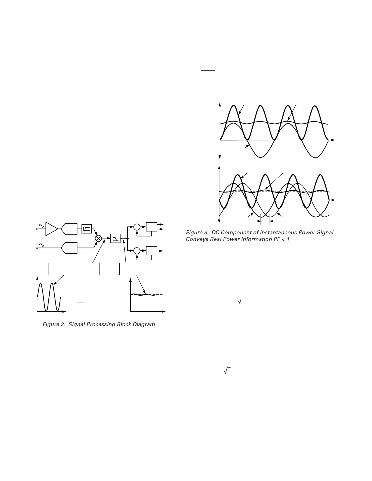
Power Factor Considerations
The method used to extract the real power information from the
instantaneous power signal (i.e., by low-pass filtering) is still
valid even when the voltage and current signals are not in phase.
Figure 3 displays the unity power factor condition and a DPF
(displacement power factor) = 0.5, i.e., current signal lagging
the voltage by 60°. If we assume the voltage and current waveforms
VOLTAGE
CURRENT
60؇
Figure 3. DC Component of Instantaneous Power Signal
Conveys Real Power Information PF < 1
Nonsinusoidal Voltage and Current
The real power calculation method also holds true for nonsinu-
soidal current and voltage waveforms. All voltage and current
waveforms in practical applications will have some harmonic
content. Using the Fourier Transform, instantaneous voltage
and current waveforms can be expressed in terms of their
harmonic content.
∞
v(t) = VO + 2 × ∑ Vh × sin(hωt + αh )
(2)
h≠0
where:
v(t) = The instantaneous voltage
VO = The average value
Vh = The rms value of voltage harmonic h
and
␣h = The phase angle of the voltage harmonic
∞
i(t ) = IO + 2 × ∑ Ih × sin(hωt + βh ) (3)
h≠0
where:
i(t) = The instantaneous current
IO = The dc component
Ih = The rms value of current harmonic h
and
h = The phase angle of the current harmonic
–10–
REV. PrA
Share Link: 