AD9389A Ver la hoja de datos (PDF) - Analog Devices
Número de pieza
componentes Descripción
Fabricante
AD9389A Datasheet PDF : 12 Pages
| |||
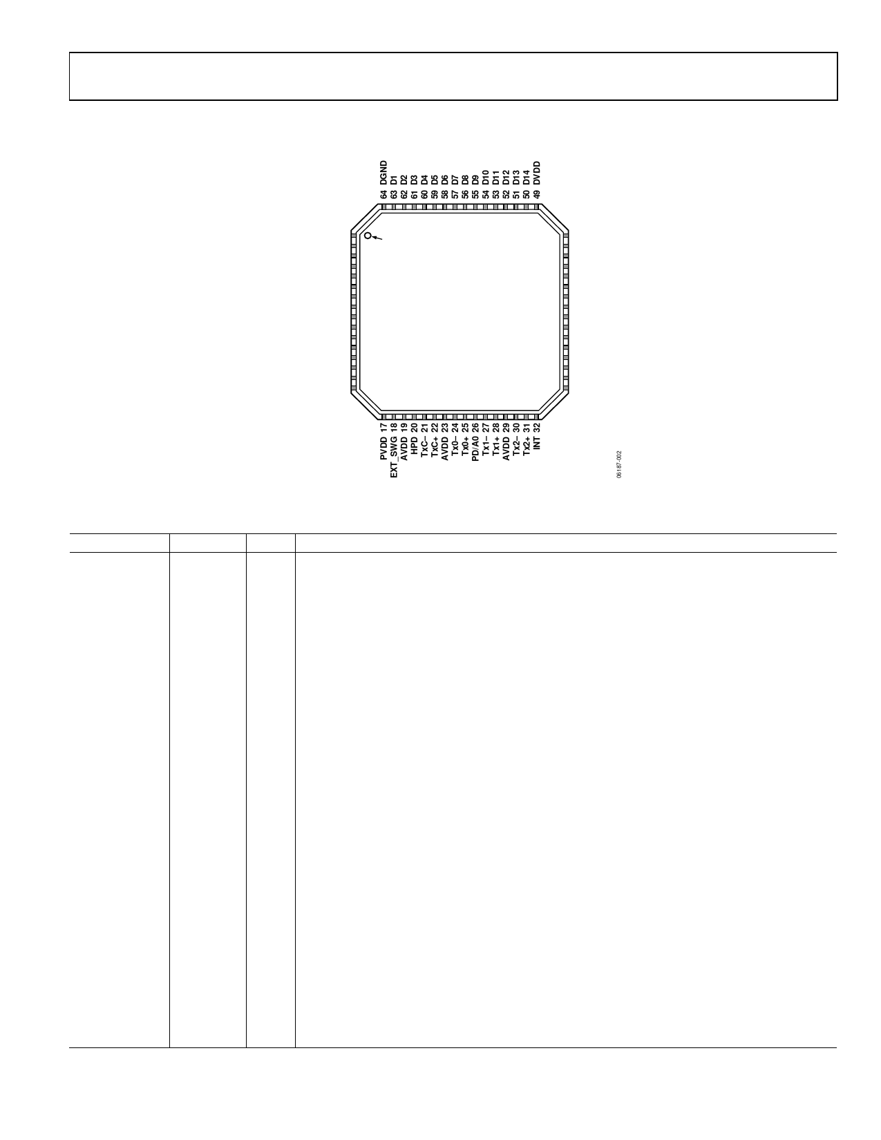
PIN CONFIGURATION AND FUNCTION DESCRIPTIONS
AD9389A
DVDD 1
D0 2
DE 3
HSYNC 4
VSYNC 5
CLK 6
S/PDIF 7
MCLK 8
I2S0 9
I2S1 10
I2S2 11
I2S3 12
SCLK 13
LRCLK 14
PVDD 15
PVDD 16
PIN 1
INDICATOR
AD9389A
TOP VIEW
(Not to Scale)
NC = NO CONNECT
48 DVDD
47 D15
46 D16
45 D17
44 D18
43 D19
42 D20
41 D21
40 D22
39 D23
38 NC
37 NC
36 SDA
35 SCL
34 DDCSDA
33 DDCSCL
Figure 2. Pin Configuration
Table 3. Pin Function Descriptions
Pin No.
Mnemonic Type1
2, 39 to 47,
50 to 63
D[23:0]
I
6
CLK
I
3
DE
I
4
HSYNC
I
5
VSYNC
I
18
EXT_SW I
20
HPD
I
7
S/PDIF
I
8
MCLK
I
9 to 12
I2S[3:0]
I
13
SCLK
I
14
LRCLK
I
26
PD/A0
I
21, 22
TxC−/TxC+ O
31, 32
Tx2−/Tx2+ O
27, 28
Tx1−/Tx1+ O
24, 25
Tx0−/Tx0+ O
32
INT
O
19, 23, 29
AVDD
P
Description
Video Data Input. Digital input in RGB or YCbCr format. Supports CMOS logic levels from 1.8 V to 3.3 V.
Video Clock Input. Supports CMOS logic levels from 1.8 V to 3.3 V.
Data Enable Bit for Digital Video. Supports CMOS logic levels from 1.8 V to 3.3 V.
Horizontal SYNC Input. Supports CMOS logic levels from 1.8 V to 3.3 V.
Vertical SYNC Input. Supports CMOS logic levels from 1.8 V to 3.3 V.
Sets internal reference currents. Place 887 Ω resistor (1% tolerance) between this pin and ground.
Hot Plug Detect Signal. This indicates to the interface whether the receiver is connected. 1.8 V to
5.0 V CMOS logic level.
S/PDIF (Sony/Philips Digital Interface) Audio Input. This is the audio input from a Sony/Philips
digital interface. Supports CMOS logic levels from 1.8 V to 3.3 V.
Audio Reference Clock. 128 × N × fS with N = 1, 2, 3, or 4. Set to 128 × sampling frequency (fS),
256 × fS, 384 × fS, or 512 × fS. 1.8 V to 3.3 V CMOS logic level.
I2S Audio Data Inputs. These represent the eight channels of audio (two per input) available
through I2S. Supports CMOS logic levels from 1.8 V to 3.3 V.
I2S Audio Clock. Supports CMOS logic levels from 1.8 V to 3.3 V.
Left/Right Channel Selection. Supports CMOS logic levels from 1.8 V to 3.3 V.
Power-Down Control and I2C Address Selection. The I2C address and the PD polarity are set by the
PD/A0 pin state when the supplies are applied to the AD9389A. 1.8 V to 3.3 V CMOS logic level.
Differential Clock Output. Differential clock output at pixel clock rate; transition minimized
differential signaling (TMDS) logic level.
Differential Output Channel 2. Differential output of the red data at 10 × the pixel clock rate;
TMDS logic level.
Differential Output Channel 1. Differential output of the green data at 10 × the pixel clock rate;
TMDS logic level.
Differential Output Channel 0. Differential output of the blue data at 10 × the pixel clock rate;
TMDS logic level.
Interrupt. CMOS logic level. A 2 kΩ pull up resistor to interrupt the microcontroller IO supply is
recommended.
1.8 V Power Supply for TMDS Outputs.
Rev. 0 | Page 5 of 12
Share Link: 