MXED102 Ver la hoja de datos (PDF) - Clare Inc => IXYS
Número de pieza
componentes Descripción
Fabricante
MXED102 Datasheet PDF : 20 Pages
| |||
MXED102
Preliminary
PRELIMINARY ELECTRICAL DATA SHEET
This document is a specification for a digital data driver for Passive Matrix Organic Light Emitting Diode (OLED) and
Polymer Light Emitting displays (PLED, PolyLED, LEP, . . . ,etc) with anodes connected to the columns. The output
stage of each channel has a resistive switch to an on chip generated voltage used during precharge and a current
source used during data output to minimize non-uniformity caused by spatial and temporal variations of the LED
characteristics and by line resistances. The data driver chip is manufactured in a high voltage (30 V) CMOS process
and provided in bumped die and TCP (Tape Carrier Package) form.
Description of Operation:
Overview: The MXED102 is configured via a serial port, and pixel data is updated on a per-row basis via a parallel
data bus.
Dynamic Pixel Control: Gray-Scale Control data is loaded into the 6-bit Column Exposure Counters each row scan
time, while the previously loaded data is being output to the OLED Display Panel. The control data sets the expo-
sure time from 0 to 63 Exposure Clock times. Successive counters are accessed upon coincidence with the token
bit, which is shifted the length of the MXED102 by the Token Shift Clock. In 6-bit Data Mode, Databus C {DC(5-0)}
is used to enter per-pixel data, and the Token traverses length of the Chip in 240 Token Shift Clocks. In 18-bit Data
Mode, Databusses A, B, and C are used to load three successive pixels in parallel, and the Token traverses length
of the Chip in 80 Token Shift Clocks.
Chip Configuration: A display controller may use the serial bus to set the characteristics of all column driver ICs by
writing to all column driver ICs in parallel. During write, the controller writes the entire data packet. The controller
can also interrogate a single column driver IC, whose MASTER pin is pulled high. Only one column driver IC on a
given bus can be designated as master. During read, the controller writes the preamble, start of frame delimiter, reg-
ister address, and turn around bits. It then tri-states for the bus tri-state and data bits and reads the data.
Color/Monochrome: The MXED102 supports three-each interleaved column Current Magnitude settings and three
Precharge Voltages, A,B and C, which may be mapped to R,G,B. Monochrome mode is selected by setting the
Color control bit to zero, in which case the Current Magnitude and Precharge Voltage is common.
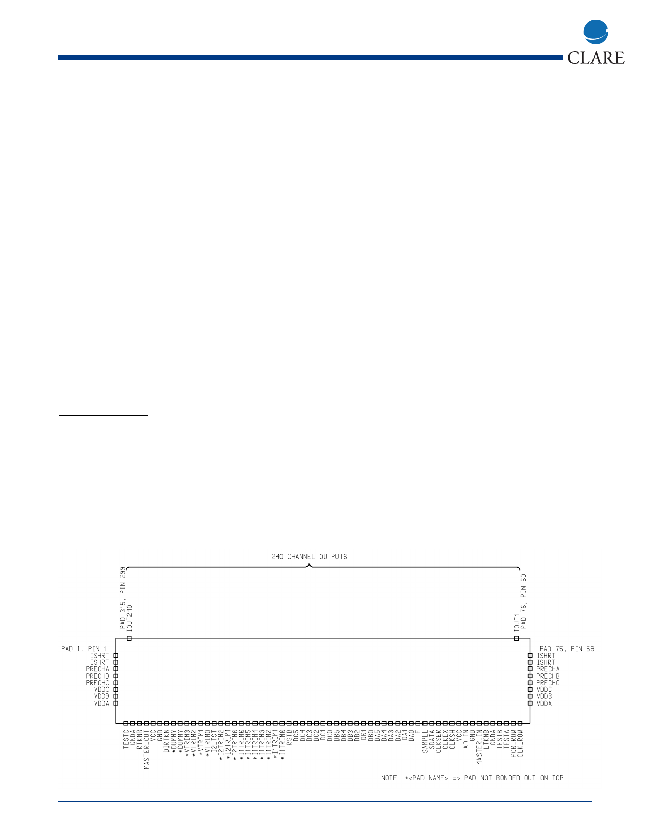
Package and Pin Out
Below is a diagram of the chip pinout:
MXED102 OLED/PLED Column Driver IC Pad Order
(NOT TO SCALE)
(DIE NOT FLIPPED)
2
www.clare.com
Rev. 2
Share Link: 