AD606 Ver la hoja de datos (PDF) - Analog Devices
Número de pieza
componentes Descripción
Fabricante
AD606 Datasheet PDF : 12 Pages
| |||
8/30/99 9 AM
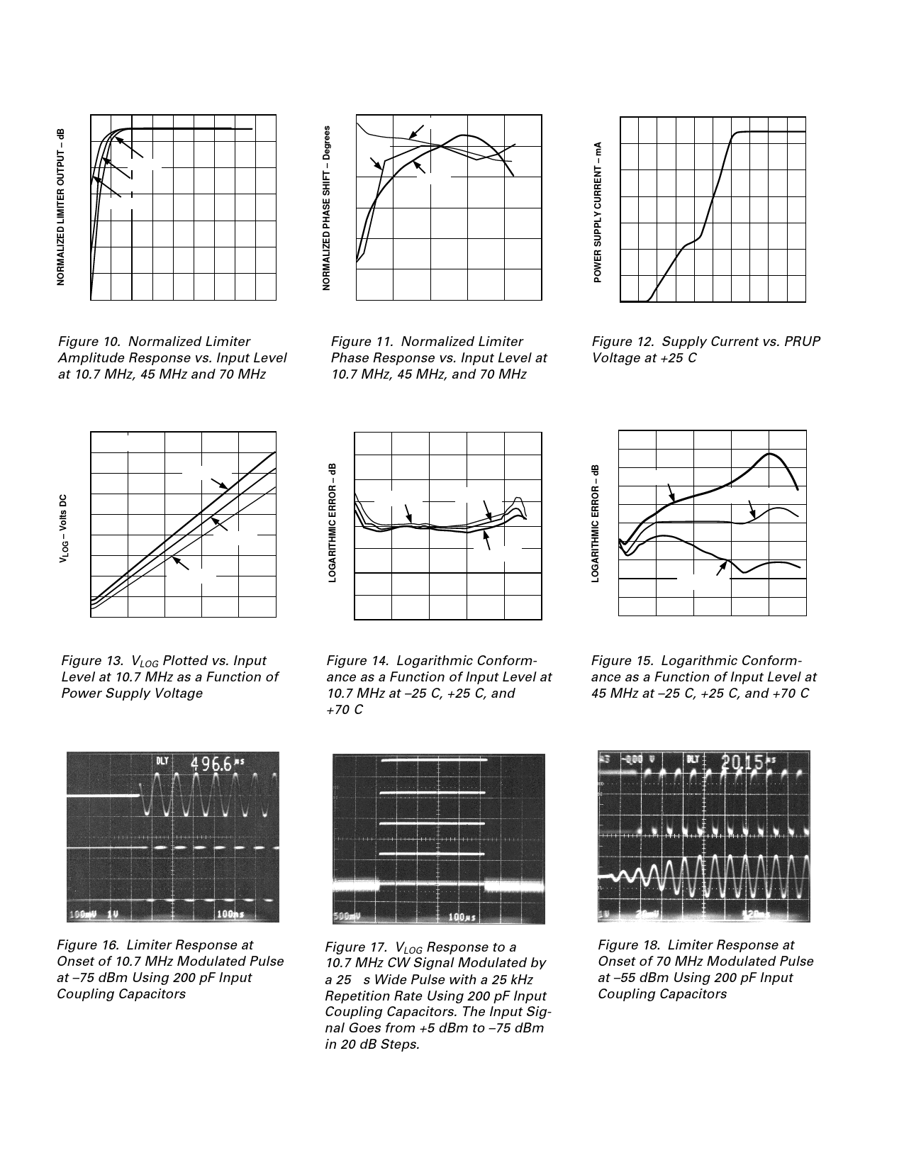
AD606–Typical Performance Characteristics
0.5
–0.5
–1.5
70MHz
45MHz
–2.5
10.7MHz
–3.5
–4.5
–5.5
–6.5
–80 –70 –60 –50 –40 –30 –20 –10 0 20
INPUT LEVEL – dBm
Figure 10. Normalized Limiter
Amplitude Response vs. Input Level
at 10.7 MHz, 45 MHz and 70 MHz
5
0 45MHz
–5
10.7MHz
70MHz
–10
–15
–20
–25
–80 –60 –40 –20
0
20
INPUT LEVEL – dBm
Figure 11. Normalized Limiter
Phase Response vs. Input Level at
10.7 MHz, 45 MHz, and 70 MHz
14
12
10
8
6
4
2
0
0 0.5 1 1.5 2 2.5 3 3.5 4 4.5 5
PRUP VOLTAGE – Volts
Figure 12. Supply Current vs. PRUP
Voltage at +25°C
4.5
TA = +25؇C
4
3.5
VS = 5.5V
3
2.5
2
VS = 5V
1.5
1
VS = 4.5V
0.5
0
–80 –60 –40 –20
0
10
INPUT POWER – dBm
Figure 13. VLOG Plotted vs. Input
Level at 10.7 MHz as a Function of
Power Supply Voltage
4
3
2
1
TA = –25؇C
TA = +25؇C
0
–1
TA = +70؇C
–2
–3
–4
–80 –60
–40
–20
0
10
INPUT AMPLITUDE – dBm
Figure 14. Logarithmic Conform-
ance as a Function of Input Level at
10.7 MHz at –25°C, +25°C, and
+70°C
5
4
3
TA = –25؇C
2
1
TA = +25؇C
0
–1
–2
–3
TA = +70؇C
–4
–5
–80 –60 –40 –20
0
10
INPUT AMPLITUDE – dBm
Figure 15. Logarithmic Conform-
ance as a Function of Input Level at
45 MHz at –25°C, +25°C, and +70°C
Figure 16. Limiter Response at
Onset of 10.7 MHz Modulated Pulse
at –75 dBm Using 200 pF Input
Coupling Capacitors
Figure 17. VLOG Response to a
10.7 MHz CW Signal Modulated by
a 25 µs Wide Pulse with a 25 kHz
Repetition Rate Using 200 pF Input
Coupling Capacitors. The Input Sig-
nal Goes from +5 dBm to –75 dBm
in 20 dB Steps.
Figure 18. Limiter Response at
Onset of 70 MHz Modulated Pulse
at –55 dBm Using 200 pF Input
Coupling Capacitors
–10–
REV. B
Share Link: 