A1225LLTTR-T Ver la hoja de datos (PDF) - Allegro MicroSystems
Número de pieza
componentes Descripción
Fabricante
A1225LLTTR-T Datasheet PDF : 12 Pages
| |||
A1225, A1227
and A1229
Hall Effect Latch for High Temperature Operation
Functional Description and Application Information
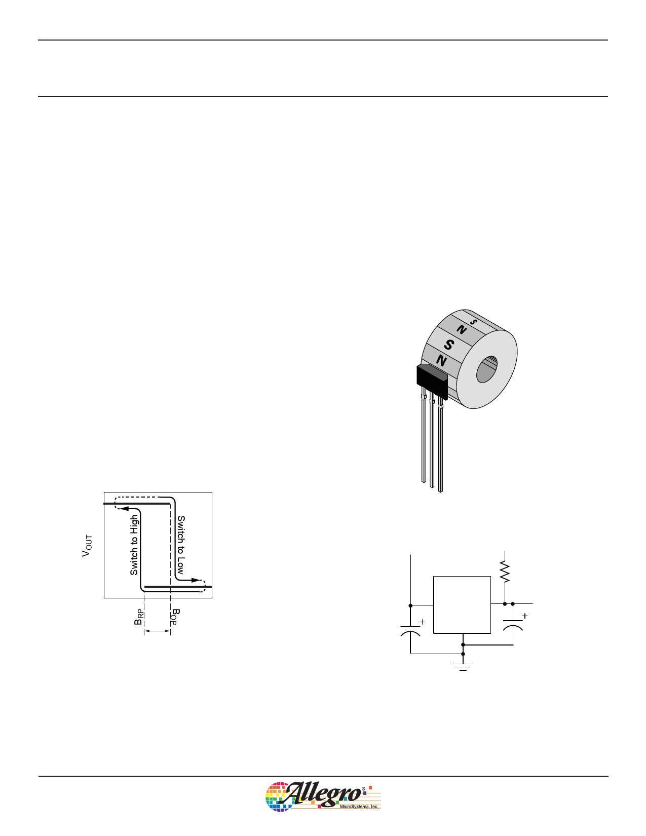
Switching Behavior
The output of the A1225, A1227, and A1229 devices switches
low (turns on) when a magnetic field perpendicular to the Hall
element exceeds the operate point threshold, BOP (see figure 1).
After turn-on, the output is capable of sinking 25 mA and the
output voltage is VOUT(sat). Notice that the device latches; that is,
a south pole of sufficient strength towards the branded surface
of the device turns the device on, and the device remains on with
removal of the south pole.
Application Information
The simplest form of magnet that will operate these devices is a
ring magnet, as shown in figure 2. Other methods of operation
are possible.
In three-wire applications the device output is connected through
a pull-up resistor to the supply pin or separate battery voltage
(figure 3). Switching of the output signal indicates sufficient
change of the magnetic field.
When the magnetic field is reduced below the release point, BRP ,
the device output goes high (turns off). The difference between
the magnetic operate point and release point is the hysteresis,
BHYS, of the device. This built-in hysteresis allows clean switch-
ing of the output, even in the presence of external mechanical
vibration and electrical noise.
When the device is powered-on in the hysteresis range, less than
BOP and higher than BRP, the device output goes high. The correct
output state is attained after the first excursion beyond BOP or
BRP .
V+
VCC
0
B–
BHYS
VOUT(sat)
B+
Figure 1. Output switching characteristics
Figure 2. Typical magnetic target configuration using a ring magnet
V+
CBYPASS
VPULLUP
A122x
VCC
VOUT
GND
RPULLUP
Device
Output
CL
(Optional)
Figure 3. Typical 3-wire application circuit
Allegro MicroSystems, Inc.
9
115 Northeast Cutoff
Worcester, Massachusetts 01615-0036 U.S.A.
1.508.853.5000; www.allegromicro.com
Share Link: 