DS2502X1 Ver la hoja de datos (PDF) - Dallas Semiconductor -> Maxim Integrated
Número de pieza
componentes Descripción
Fabricante
DS2502X1 Datasheet PDF : 22 Pages
| |||
DS2502
the 1-Wire line as well as indicate to the bus master how many and what types of devices are present. The
protocol required for these ROM Function Commands is described in Figure 9. After a ROM Function
Command is successfully executed, the memory functions that operate on the EPROM portions of the
DS2502 become accessible and the bus master may issue any one of the five Memory Function
Commands specific to the DS2502 to read or program the various data fields. The protocol for these
Memory Function Commands is described in Figure 5. All data is read and written least significant bit
first.
64-BIT LASERED ROM
Each DS2502 contains a unique ROM code that is 64 bits long. The first 8 bits are a 1-Wire family code.
The next 48 bits are a unique serial number. The last 8 bits are a CRC of the first 56 bits. (See Figure 3).
The 64-bit ROM and ROM Function Control section allow the DS2502 to operate as a 1-Wire device and
follow the 1-Wire protocol detailed in the section “1-Wire Bus System.” The memory functions required
to read and program the EPROM sections of the DS2502 are not accessible until the ROM function
protocol has been satisfied. This protocol is described in the ROM functions flow chart (Figure 9). The 1-
Wire bus master must first provide one of four ROM function commands: 1) Read ROM, 2) Match ROM,
3) Search ROM, or 4) Skip ROM. After a ROM function sequence has been successfully executed, the
bus master may then provide any one of the memory function commands specific to the DS2502 (Figure
6).
The 1-Wire CRC of the lasered ROM is generated using the polynomial X8 + X5 + X4 + 1. Figure 4
shows a hardware implementation of this CRC generator. Additional information about the Dallas
Semiconductor 1-Wire Cyclic Redundancy Check is available in Application Note 27. The shift register
acting as the CRC accumulator is initialized to 0. Then starting with the least significant bit of the family
code, 1 bit at a time is shifted in. After the 8th bit of the family code has been entered, then the serial
number is entered. After the 48th bit of the serial number has been entered, the shift register contains the
CRC value. Shifting in the 8 bits of CRC should return the shift register to all 0s.
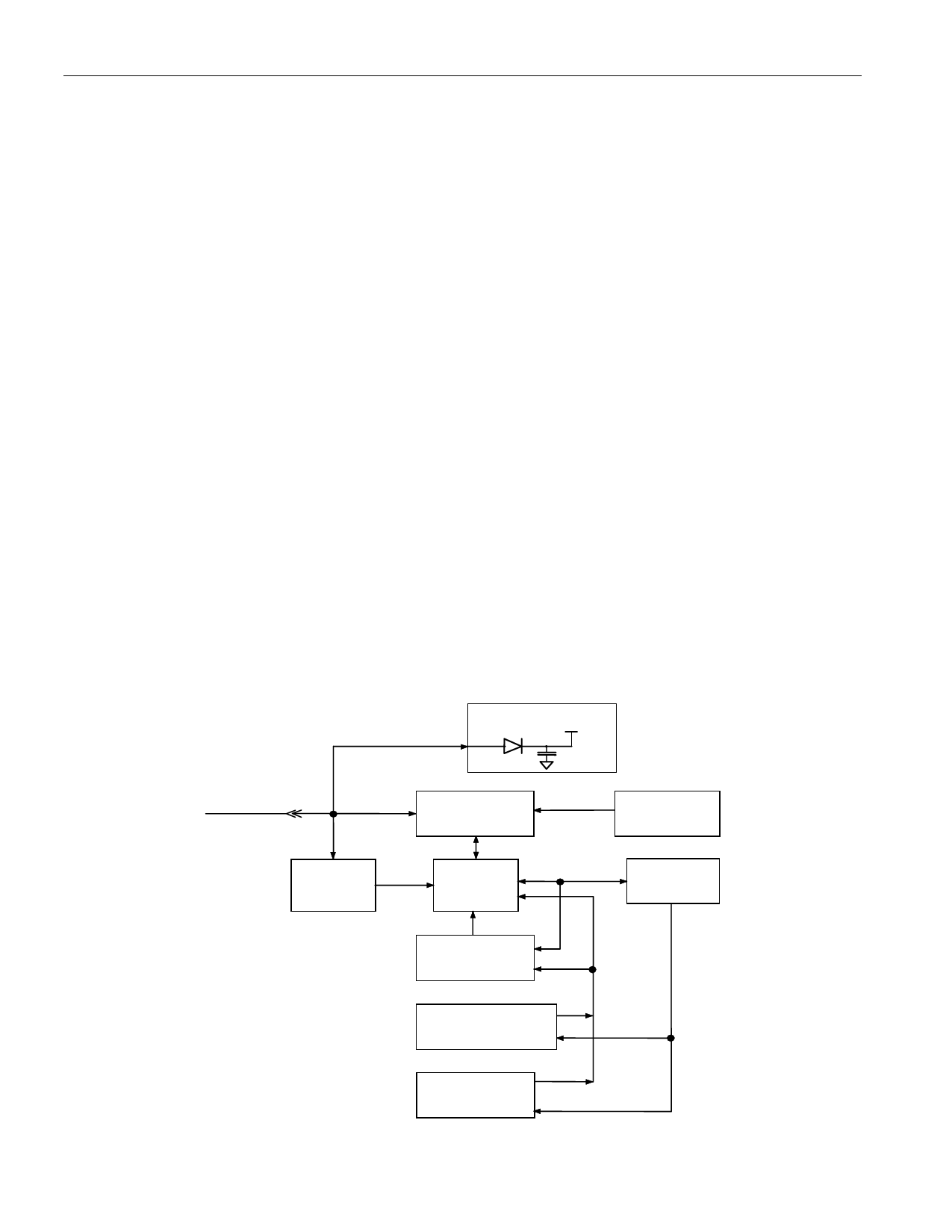
DS2502 BLOCK DIAGRAM Figure 1
PARASITE POWER
1-WIRE BUS
DATA
PROGRAM
VOLTAGE
DETECT
1-WIRE FUNCTION
CONTROL
MEMORY
FUNCTION
CONTROL
8-BIT CRC
GENERATOR
1024-BIT EPROM
(4 PAGES OF 32 BYTES)
EPROM
STATUS BYTES
3 of 22
64-BIT LASERED
ROM
8-BIT
SCRATCHPAD
Share Link: 