27C010 Ver la hoja de datos (PDF) - Fairchild Semiconductor
Número de pieza
componentes Descripción
Fabricante
27C010 Datasheet PDF : 10 Pages
| |||
AC Test Conditions
Output Load
1 TTL Gate and CL = 100 pF (Note 8)
Input Rise and Fall Times
≤5 ns
Input Pulse Levels
0.45V to 2.4V
Timing Measurement Reference Level
Inputs
Outputs
0.8V and 2V
0.8V and 2V
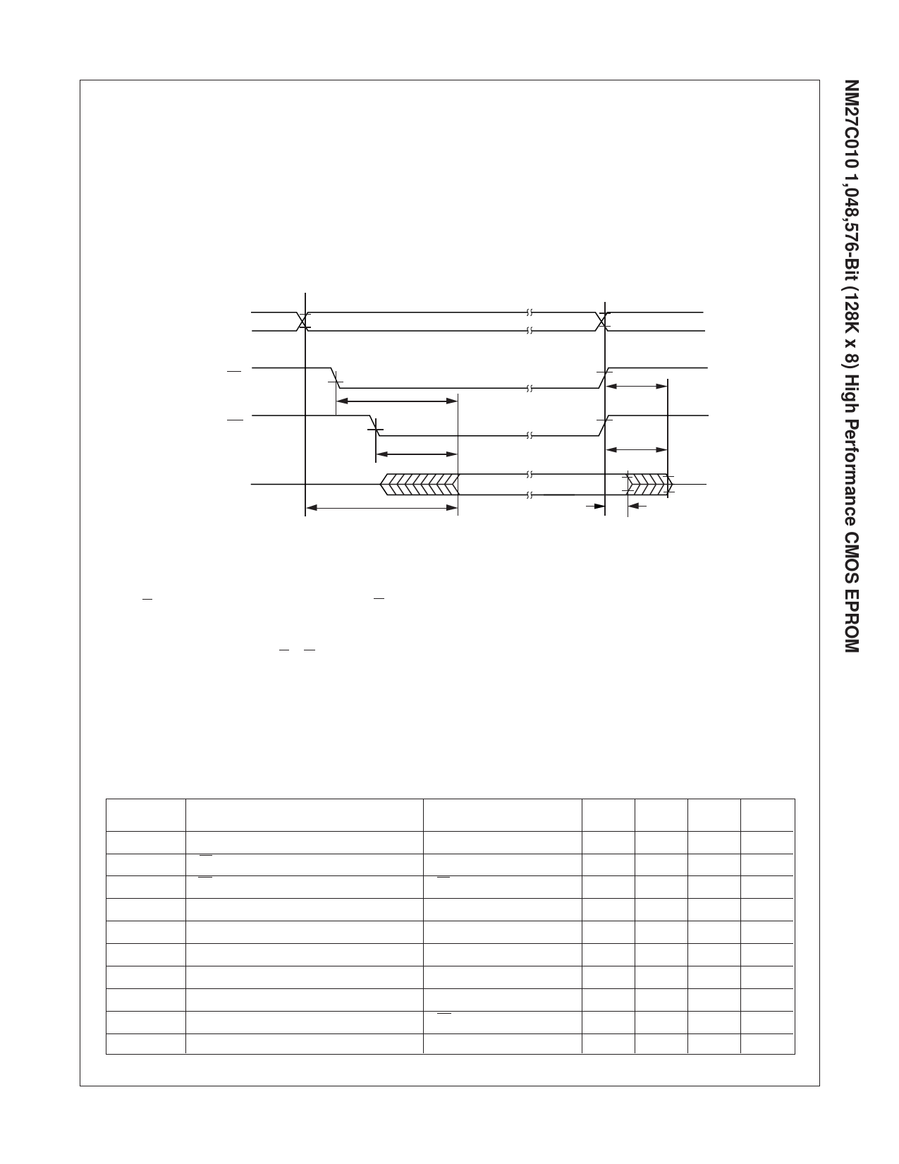
AC Waveforms (Note 6), (Note 7), and (Note 9)
ADDRESS
2V
0.8V
Address Valid
CE 2V
0.8V
2V
OE 0.8V
2V
OUTPUT
0.8V
tCE
Hi-Z
tACC
(Note 3)
tOE
(Note 3)
Valid Output
tCF
(Note 4, 5)
tDF
(Note 4, 5)
tOH
Hi-Z
DS010798-4
Note 1: Stresses above those listed under “Absolute Maximum Ratings” may cause permanent damage to the device. This is a stress rating only and functional operation of
the device at these or any other conditions above those indicated in the operational sections of this specification is not implied. Exposure to absolute maximum rating conditions
for extended periods may affect device reliability.
Note 2: This parameter is only sampled and is not 100% tested.
Note 3: OE may be delayed up to tACC - tOE after the falling edge of CE without impacting tACC.
Note 4: The tDF and tCF compare level is determined as follows:
High to TRI-STATE®, the measured VOH1 (DC) - 0.10V;
Low to TRI-STATE, the measured VOL1 (DC) + 0.10V.
Note 5: TRI-STATE may be attained using OE or CE.
Note 6: The power switching characteristics of EPROMs require careful device decoupling. It is recommended that at least a 0.1 µF ceramic capacitor be used on every device
between VCC and GND.
Note 7: The outputs must be restricted to VCC + 1.0V to avoid latch-up and device damage.
Note 8: 1 TTL Gate: IOL = 1.6 mA, IOH = -400 µA.
CL: 100 pF includes fixture capacitance.
Note 9: VPP may be connected to VCC except during programming.
Note 10: Inputs and outputs can undershoot to -2.0V for 20 ns Max.
Programming Characteristics (Note 11), (Note 12), (Note 13), and (Note 14)
Symbol
tAS
tOES
tCES
tDS
tVPS
tVCS
tAH
tDH
tDF
tPW
Parameter
Address Setup Time
OE Setup Time
CE Setup Time
Data Setup Time
VPP Setup Time
VCC Setup Time
Address Hold Time
Data Hold Time
Output Enable to Output Float Delay
Program Pulse Width
Conditions
OE = VIH
CE = VIL
Min
1
1
1
1
1
1
0
1
0
45
Typ
50
Max
60
105
Units
µs
µs
µs
µs
µs
µs
µs
µs
ns
µs
4
www.fairchildsemi.com
Share Link: 