2623CSA Ver la hoja de datos (PDF) - Agere -> LSI Corporation
Número de pieza
componentes Descripción
Fabricante
2623CSA Datasheet PDF : 8 Pages
| |||
10 Gbits/s Lithium Niobate Electro-Optic Modulator
Data Sheet
May 2001
Optical/Electrical Characteristics (continued)
Electrical Signal Input
Electrical signal input is made through SMA coaxial connectors. The standard device includes an internal termina-
tion network. Care must be taken not to exceed the recommended 8 in./lb. of torque when making connections to
these inputs. High-frequency coaxial cable is recommended.
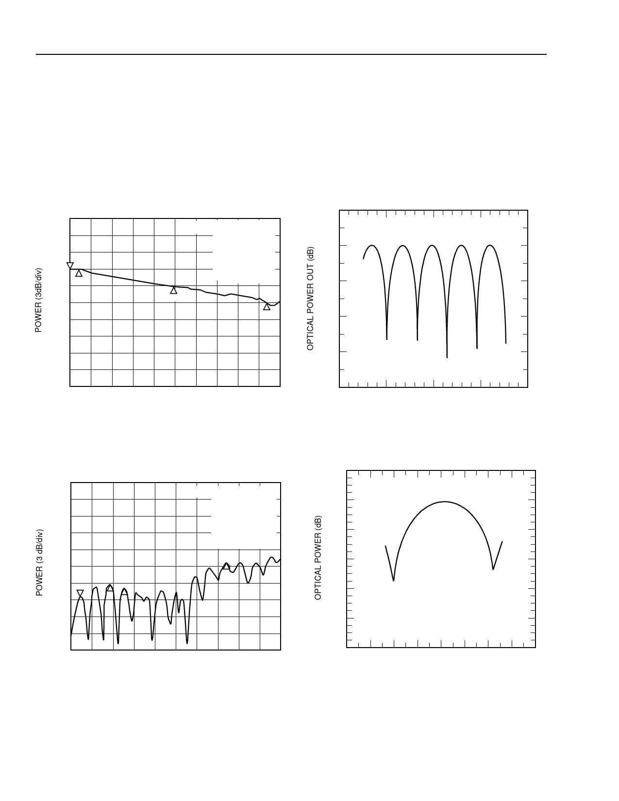
Characteristic Curves
CH1 E/O LOG MAG3 dB/ REF –55.48 dB 1: –55.846 dB
0
W/A
1. 130 000 000 GHz
2. –55.476 dB
dBe
COR
AVG 1
4
SMA 2
HID
0.9248 GHz
–10
3. –58.476 dB
9.9690 GHz
4. –61.766 dB
18.76 48 GHz
–20
3
4
–30
–40
START .130 000 000 GHz STOP 20.000 000 000 GHz
FREQUENCY
1-1058(F)
Figure 3. Magnitude of Electro-Optic Response,
0.130 GHz—20 GHz.
.
CH1 S11 LOG MAG 5 dB/ REF 0 dB 1: –18.896 dB
dBe
COR
HID
1. 924 000 000 GHz
2. –15.278 dB
3.7006 GHz
3. –16.27 dB
5.0975 GHz
4. –8.7734 dB
14.7344 GHz
4
1
23
–50
–20
–10
0
10
MODULATOR dc BIAS VOLTAGE (V)
20
1-1060(F)
Figure 5. Output Power vs. Bias Voltage
0
–10
–20
–30
–40
–50
START .130 000 000 GHz STOP 20.000 000 000 GHz
FREQUENCY
Figure 4. S11, 0.130 GHz—20 GHz
1-1059(F)
–60
–40 –30 –20 –10 0
10 20 30 40
ATTENUATOR BIAS VOLTAGE (V)
1-898 (C)
START = –23.98 V
STOP = 25.58 V
1-1061(F)
Figure 6. Optical Power vs. Attenuator Bias Voltage
4
Agere Systems Inc.
Share Link: 