SC91415AP Ver la hoja de datos (PDF) - Silan Microelectronics
Número de pieza
componentes Descripción
Fabricante
SC91415AP Datasheet PDF : 23 Pages
| |||
Silan
Semiconductors
SC91415 SERIES
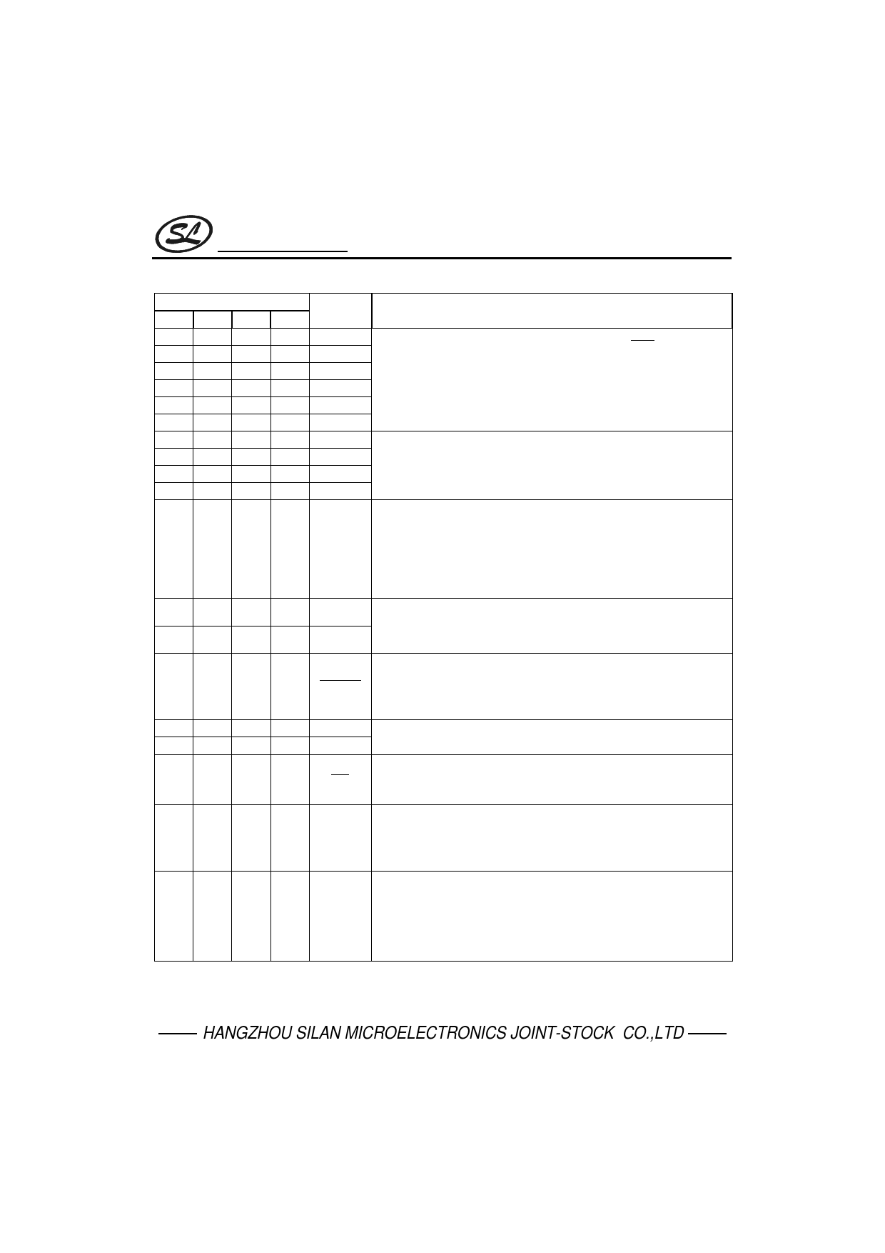
PIN DESCRIPTION
Pin No.
AP BP CK DK
13 15 16 18
14 16 17 19
15 17 18 20
16 18 19 21
--
-- 22 24
--
--
1
1
5
5
6
6
4
4
5
5
3
3
4
4
1
1
2
2
2
2
3
3
6
6
7
7
7
7
8
8
Pin Name
ROW1
ROW2
ROW3
ROW4
ROW5
ROW6
COL1
COL2
COL3
COL5
COL4/KT
XIN
XOUT
Description
Keyboard scan pins of row group. In idle state ( HKS is “High” and
HFO is “Low”), these pins stay “High impedance” level to prevent
power consumption. Otherwise, these pins switch to “High” level for
detecting keyboard entry. These pins will output 600Hz signal while
keyboard is scanning.
Keyboard scan pins of column group. In idle state, these pins stay
“High impedance” level. Otherwise these pins switch to “Low” level for
detecting keyboard entry. These pins will output 600Hz signal while
keyboard is scanning.
The fourth column group pin of the keyboard that also provides the
keytone output. Normally, this pin stays “Low” level for detecting
keyboard entry. After a valid keyboard entry, this pin will output keying
confirmation tone that is 600 Hz signal and 30 ms duration. To
prevent signal interference, while DTMF issue, it will disable key tone
output except function key.
Oscillator input and output pins. A 3.579545MHz crystal or ceramic
resonator must be crossed connection to XIN and XOUT pins which
generate system clock.
The Tone/Pulse MUTE signal output pin that is NMOS open-drain
output structure. This pin will switch to “Low” level during Tone/Pulse
8
8
9
9
XMUTE dialing and hold function. Otherwise, this pin stays “High impedance”
level.
11 13 14 16
VDD Positive and negative power supply input pins. Recommended
9
9 10 10
VSS operating voltage from 2.0Vdc to 5.5Vdc.
-- 10 11 11
--
11 12 14
HFI
HFO
Handfree inputs pin which accepts falling edge signal to turn “on” or
turn “off” handfree function. This pin is hysteresis input structure and
built-in pull up resistor (typically 200kΩ).
Handfree outputs pin that is designed to control telephone line for
on-hook dialing or control speakerphone circuit for handfree
conversation. When handfree function is executed, this pin will switch
to“High”. Otherwise, this pin stays “Low” level.
The DTMF (Dual Tone Multi-Frequency) and music signals output pin.
Normally, this pin stays “Low” level. In Tone dialing mode, this pin will
10 12 13 15
DTMF output DTMF signal that is corresponding to keyboard 0 . 9, * and #
keys. Beside this, in the line hold duration, this pin will issue dual-tone
music for telephone line.
(to be continued)
HANGZHOU SILAN MICROELECTRONICS JOINT-STOCK CO.,LTD
Rev: 2.0
2001-11-13
7
Share Link: 