28F002BC Ver la hoja de datos (PDF) - Intel
Número de pieza
componentes Descripción
Fabricante
28F002BC Datasheet PDF : 37 Pages
| |||
E
28F002BC 2-MBIT BOOT BLOCK FLASH MEMORY
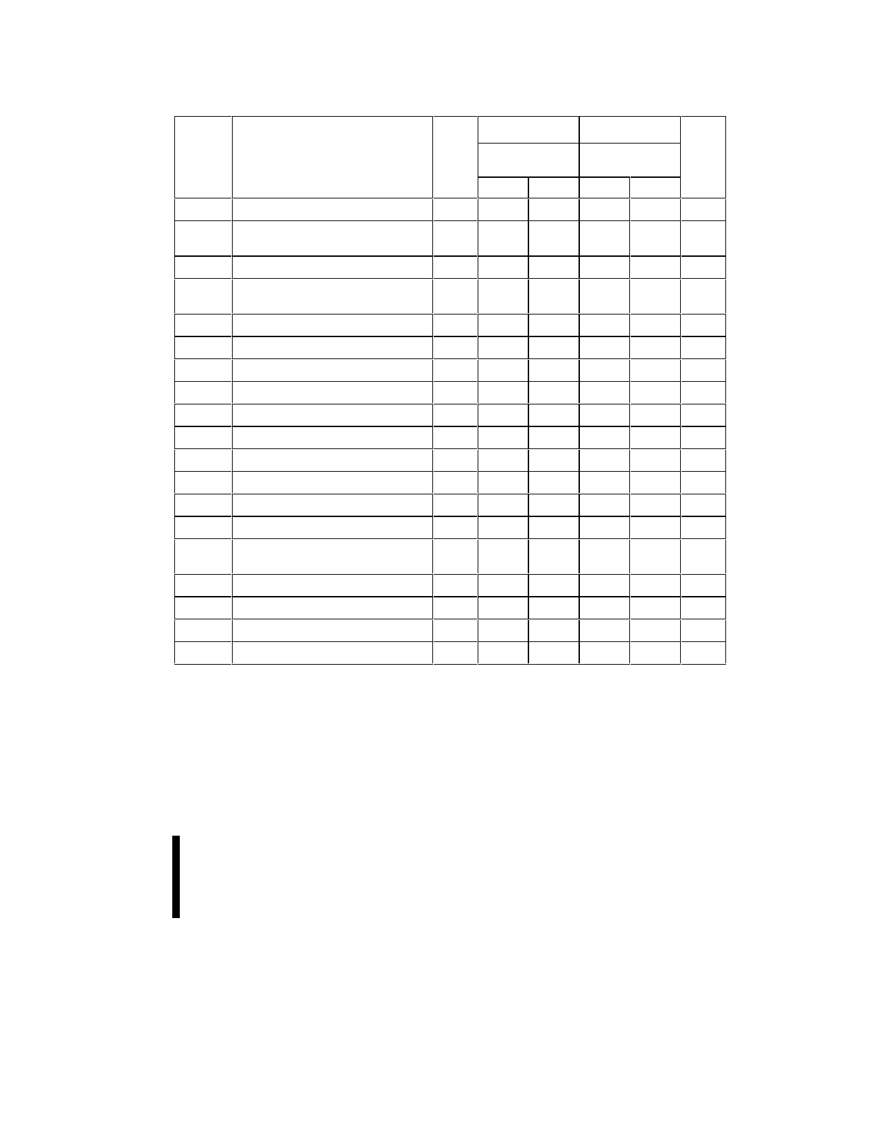
Table 10. AC Characteristics: CE#—Controlled Write Operations(1,9)
28F002BC-80 28F002BC-120
Symbol
Parameter
Notes VCC = 5V ± 10% VCC= 5V ± 10% Units
100 pF
100 pF
Min
Max
Min
Max
tAVAV
Write Cycle Time
80
120
ns
tPHEL
RP# High Recovery to CE# Going
215
215
ns
Low
tWLEL
WE# Setup to CE# Going Low
0
0
ns
tPHHEH Boot Block Lock Setup to CE# Going 6, 8
100
100
ns
High
tVPEH
VPP Setup to CE# Going High
5, 8 100
100
ns
tAVEH
Address Setup to CE# Going High
3
50
50
ns
tDVEH
Data Setup to CE# Going High
4
50
50
ns
tELEH
CE# Pulse Width
50
50
ns
tEHDX
Data Hold Time from CE# High
4
0
0
ns
tEHAX
Address Hold Time from CE# High
3
0
0
ns
tEHWH
WE # Hold Time from CE# High
0
0
ns
tEHEL
CE# Pulse Width High
30
30
ns
tEHQV1 Duration of Programming Operation 2, 5
6
6
µs
tEHQV2 Duration of Erase Operation (Boot) 2, 5, 6 0.3
0.3
s
tEHQV3 Duration of Erase Operation
2, 5
0.3
0.3
s
(Parameter)
tEHQV4 Duration of Erase Operation (Main)
2, 5
0.6
0.6
s
tQVVL
VPP Hold from Valid SRD
5, 8
0
0
ns
tQVPH
RP# VHH Hold from Valid SRD
6, 8
0
0
ns
tPHBR
Boot Block Lock Delay
7, 8
100
100
ns
NOTES:
See WE# Controlled Write Operations for notes 1 through 8.
9. Chip-Enable controlled writes: write operations are driven by the valid combination of CE# and WE# in systems where
CE# defines the write pulse-width (within a longer WE# timing waveform), all set-up, hold and inactive WE# times should
be measured relative to the CE# waveform.
PRELIMINARY
33
Share Link: 