EM84530 Ver la hoja de datos (PDF) - ELAN Microelectronics
Número de pieza
componentes Descripción
Fabricante
EM84530 Datasheet PDF : 14 Pages
| |||
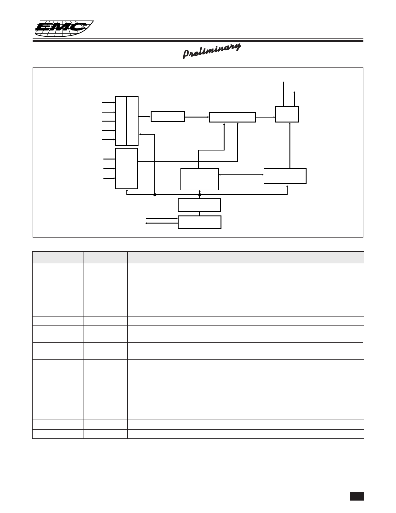
FUNCTIONAL BLOCK DIAGRAM
EM84530
2-IN-ONE MOUSE CONTROLLER
Preliminary
DATA/RXD
CLK/RTS
OPT
X1
X2
Y1
Y2
C
O
M
P
A
R
A
T
O
D
ME
OT
TE
IC
OT
NO
R
R
COUNTER
MULTIPLEXER
DATA
I/O
D
L
E
B
M
O
U
R
N
C
E
COMMAND
& STATUS
OR PNP IO
TIMING
CONTROLLER
OSCR
OSC.OUT
SYSTEM CLOCK
GENERATOR
RC
OSCILLATION
PIN DESCRIPTIONS
Symbol
I/O
OPT
I/O
OSC.OUT
O
OSCR
I
CLK/RTS
I/O
DATA/RXD
I/O
R
I
M
I/O
L
I/O
X1
I
X2
I
Y1
I
Y2
I
VSS
VDD
Function
INPUT: 200kΩ pull low to VSS.
When OPT is connected to VDD, EM84530 will enter test mode. In test mode,
L will be the output of X1,while M will be the output of X2. Toggling R key can
change these output to be Y1,Y2 respectively.
The RC oscillation clock output. Or 3mA sink current output for X, Y photo
emitters.
Connect 50kΩ±1% precise resistor for oscillation.
Connect directly to 8042 auxiliary port CLK line in PS/2 mode or connect directly
to RS-232C RTS pin in serial mode. Auto-detect the operating port by this pin.
Connect directly to 8042 auxiliary port DATA line in PS/2 mode or connect
directly to RS-232C RXD pin in serial mode.
Three key-switches inputs. 200kΩ resistor pull low.
Three step dynamic input impedance. If OSC.OUT is not connected to LEDs, the
dynamic input impedance will be off.
Use current comparator to measure photo-couples "ON", or "OFF".
Negative power.
Power line.
* This specification are subject to be changed without notice.
6.28.1999 2
Share Link: 