100319 Ver la hoja de datos (PDF) - Fairchild Semiconductor
Número de pieza
componentes Descripción
Fabricante
100319 Datasheet PDF : 6 Pages
| |||
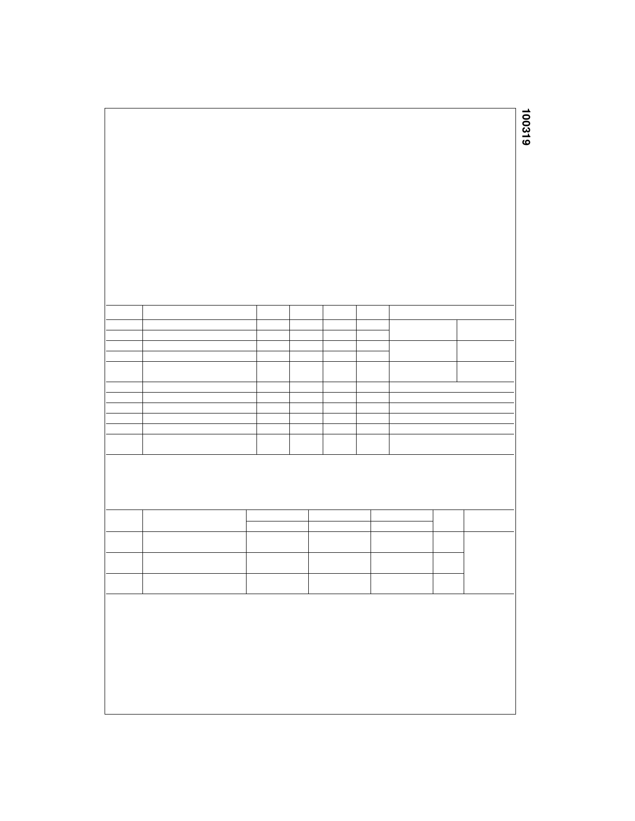
Absolute Maximum Ratings(Note 1)
Storage Temperature (TSTG)
Maximum Junction Temperature (TJ)
Pin Potential to Ground Pin (VEE)
Input Voltage (DC)
Output Current (DC Output HIGH)
ESD (Note 2)
−65°C to +150°C
+150°C
−7.0V to +0.5V
VEE to +0.5V
−100 mA
≥2000V
Recommended Operating
Conditions
Case Temperature (TC)
Commercial
0°C to +85°C
Industrial
−40°C to +85°C
Supply Voltage (VEE)
−5.7V to −4.2V
Note 1: The “Absolute Maximum Ratings” are those values beyond which
the safety of the device cannot be guaranteed. The device should not be
operated at these limits. The parametric values defined in the Electrical
Characteristics tables are not guaranteed at the absolute maximum rating.
The “Recommended Operating Conditions” table will define the conditions
for actual device operation.
Note 2: ESD testing conforms to MIL-STD-883, Method 3015.
Commercial Version
DC Electrical Characteristics (Note 3)
VEE = −4.2V to −5.7V, VCC = VCCA = GND, TC = 0°C to +85°C
Symbol
Parameter
Min
Typ
Max
Units
Conditions
VOH
VOL
VOHC
VOLC
VOLZ
VIH
VIL
IIL
IIH
IEE
IEEZ
Output HIGH Voltage
Output LOW Voltage
Output HIGH Voltage
Output LOW Voltage
Cut-Off LOW
Voltage
Input HIGH Voltage
Input LOW Voltage
Input LOW Current
Input HIGH Current
Power Supply Current, Normal
Power Supply
Current, Cut-Off
−1025
−1830
−1035
−955
−1705
−870
−1620
−1610
−1950
−1110
−1830
−119
−219
−870
−1530
100
360
−30
−75
mV
VIN = VIH(Max)
Loading with
mV
or VIL(Min)
25Ω to −2.0V
mV
VIN = VIH(Min)
Loading with
mV
or VIL(Max)
25Ω to −2.0V
mV
VIN = VIH(Min)
OE = LOW
or VIL(Max)
mV Guaranteed HIGH Signal for All Inputs
mV Guaranteed LOW Signal for All Inputs
µA
VIN = VIL(Min)
µA
VIN = VIH(Max)
mA
mA Inputs Open,
OE = LOW
Note 3: The specified limits represent the “worst case” value for the parameter. Since these values normally occur at the temperature extremes, additional
noise immunity and guardbanding can be achieved by decreasing the allowable system operating ranges. Conditions for testing shown in the tables are cho-
sen to guarantee operation under “worst case” conditions.
AC Electrical Characteristics
VEE = −4.2V to −5.7V, VCC = VCCA = GND
Symbol
Parameter
tPLH
Propagation Delay
tPHL
Data to Output
tPZH
Propagation Delay
tPHZ
OE to Output
tTLH
Transition Time
tTHL
20% to 80%, 80% to 20%
TC = 0°C
Min
Max
0.65
2.10
1.8
4.1
1.2
2.9
0.45
1.30
TC = +25°C
Min
Max
0.65
2.10
1.8
4.1
1.2
2.9
0.45
1.30
TC = +85°C
Min
Max
0.65
2.10
1.8
4.1
1.2
2.9
0.45
1.30
Units
Conditions
ns
ns Figures 1, 2
ns
3
www.fairchildsemi.com
Share Link: 