AD7951BSTZ(2015) Ver la hoja de datos (PDF) - Analog Devices
NГәmero de pieza
componentes DescripciГіn
Fabricante
AD7951BSTZ Datasheet PDF : 32 Pages
| |||
AD7951
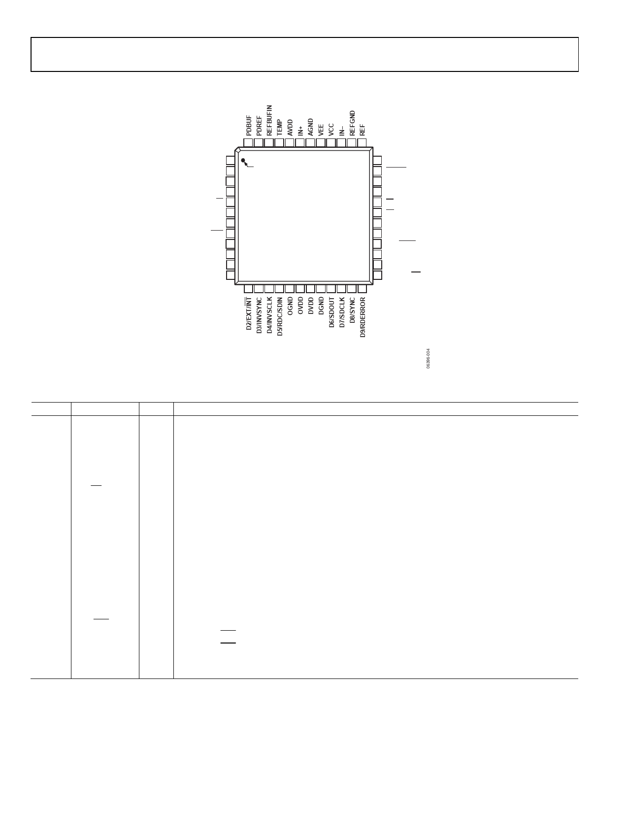
PIN CONFIGURATION AND FUNCTION DESCRIPTIONS
48 47 46 45 44 43 42 41 40 39 38 37
AGND 1
AVDD 2
AGND 3
BYTESWAP 4
OB/2C 5
WARP 6
IMPULSE 7
SER/PAR 8
NC 9
NC 10
D0/DIVSCLK[0] 11
D1/DIVSCLK[1] 12
PIN 1
AD7951
TOP VIEW
(Not to Scale)
36 BIPOLAR
35 CNVST
34 PD
33 RESET
32 CS
31 RD
30 TEN
29 BUSY
28 D13/SCCS
27 D12/SCCLK
26 D11/SCIN
25 D10/HW/SW
13 14 15 16 17 18 19 20 21 22 23 24
Data Sheet
NOTES
1. NC = NO CONNECT.
2. FOR THE LEAD FRAME CHIP SCALE PACKAGE (LFCSP), THE EXPOSED
PAD SHOULD BE CONNECTED TO VEE. THIS CONNECTION IS NOT
REQUIRED TO MEET THE ELECTRICAL PERFORMANCES.
Figure 4. Pin Configuration
Table 6. Pin Function Descriptions
Pin No. Mnemonic
Type1 Description
1, 3, 42 AGND
P
Analog Power Ground Pins. Ground reference point for all analog I/O. All analog I/O should be
referenced to AGND and should be connected to the analog ground plane of the system. In addition,
the AGND, DGND, and OGND voltages should be at the same potential.
2, 44 AVDD
P
Analog Power Pins. Nominally 4.75 V to 5.25 V and decoupled with 10 ОјF and 100 nF capacitors.
4
BYTESWAP
DI
Parallel Mode Selection (8-Bit/14-Bit). When high, the LSB is output on D[15:8] and the MSB is output
on D[7:0]; when low, the LSB is output on D[7:0] and the MSB is output on D[15:8].
5
OB/2C
DI2 Straight Binary/Binary Twos Complement Output. When high, the digital output is straight binary.
When low, the MSB is inverted resulting in a twos complement output from its internal shift register.
6
WARP
DI2 Conversion Mode Selection. Used in conjunction with the IMPULSE input per the following:
Conversion Mode WARP IMPULSE
Normal
Low Low
Impulse
Low High
Warp
High Low
Normal
High High
See the Modes of Operation section for a more detailed description.
7
IMPULSE
DI2 Conversion Mode Selection. See the WARP pin description in the previous row of this table. See the
Modes of Operation section for a more detailed description.
8
SER/PAR
DI
Serial/Parallel Selection Input.
When SER/PAR = low, the parallel mode is selected.
When SER/PAR = high, the serial modes are selected. Some bits of the data bus are used as a serial port
and the remaining data bits are high impedance outputs.
9, 10 NC
DO No Connect. Do not connect.
Rev. B | Page 8 of 32
Share Link: 